Novel metal band sawing machine and operation method thereof

A metal belt and a new type of technology, applied in metal sawing equipment, sawing machine devices, metal processing equipment, etc., can solve the problems of rising power loss, unstable center of gravity of machine tools, and unequal stress points, and achieve stable stress structure. The effect of preventing pollution of the working environment and convenient operation

Pending Publication Date: 2022-05-13
浙江中德利机床有限公司
View PDF0 Cites 0 Cited by
  • Summary
  • Abstract
  • Description
  • Claims
  • Application Information

AI Technical Summary

Problems solved by technology

Under this background, the sawing machine began to undergo major changes. At present, the metal band sawing machines on the market have relatively large defects in lifting and supporting. The lifting of the metal band sawing machine is mainly two aspects of the main column and the auxiliary column. The support and the saw beam will form an included angle. Originally, the oil cylinder is rising vertically, but due to the problem of the support position, the rising force is decomposed into two forces, one is rising and the other is pushing forward. This not only wastes power but also makes the sawing machine useful. Forward thrust, this force will cause the center of gravity of the machine tool to be unstable and saw off, and the rising force will also cause unnecessary loss, and the position of the auxiliary column of the existing sawing machine is basically on the back of the sawing beam, and the structure is also formed by welding rectangular tubes , one is that the force point is completely wrong, and the other is that the force is too small and the structure is not easy to use. At the same time, the cutting effect of the existing metal band sawing machine is poor, so it is necessary to make improvements

Method used


Image

  • Novel metal band sawing machine and operation method thereof
  • Novel metal band sawing machine and operation method thereof
  • Novel metal band sawing machine and operation method thereof

Examples


Embodiment 1

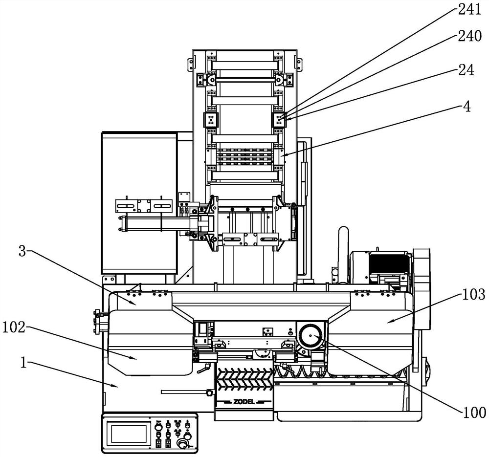
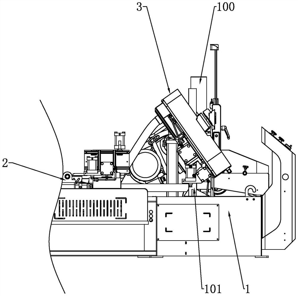
[0046] like Figure 1 to Figure 7 As shown, the embodiment of the present application provides a new type of metal band sawing machine, including a base 1, a feeding device 2, a transmission system, a saw frame 3, a guide, a cooling system and a hydraulic system, and also includes: a column, which includes a main column 100 And auxiliary column 101; Clamping device, clamping device comprises front clamping part and rear clamping part; Saw frame box, saw frame box comprises left saw frame box 102 and right saw frame box 103; Saw beam, saw beam is arranged on On the saw frame 3; the saw blade, the saw blade is arranged in the saw frame box; the main column 100 also includes: a lifting large column cover; the main column support structure, the main column support structure includes an adjustable lifting support seat; the auxiliary column 101 also includes: a support side column; guiding seat;

[0047] Among them, the transmission system is used to drive the saw blade, and the hydr...

Embodiment 2

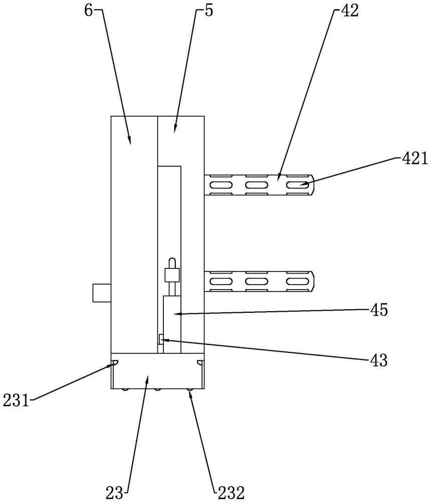
[0050] In this embodiment, in addition to including the structural features of the preceding embodiments, further feeding device 2 also includes: feeding rack 21, on which feeding rack 21 is provided with some feeding rollers 22; several cleaning units 4, and cleaning unit 4 is arranged on feeding rack 21 and between some feed rollers 22; the cleaning unit 4 also includes: an adsorption box 5, the left side wall of the adsorption box 5 is provided with some through holes; a cleaning box 6, and the cleaning box 6 is arranged on the right side of the adsorption box 5; Plate 41, mounting plate 41 is arranged in the adsorption box 5; Some telescopic adsorption rods 42, telescopic adsorption rods 42 are hollow rods, the rod wall of the telescopic adsorption rods 42 is provided with a wind chamber 420, and the telescopic adsorption rods 42 are provided with adsorption holes 421; blower 43, the blower 43 is arranged on the mounting plate 41, the blower 43 communicates with the air cha...

Embodiment 3

[0055] In this embodiment, in addition to the structural features of the foregoing embodiments, the further cleaning box 6 also includes: an air inlet cavity 61, a movable plug 7 is arranged in the air inlet cavity 61; a filter cavity 62, a filter plate is arranged in the filter cavity 62 8; the air outlet chamber 63, the second exhaust fan 9 and the electrical connection block 10 are arranged in the air outlet chamber 63; the cleaning chamber 64, the movable partition 11 and the water outlet 12 are arranged in the cleaning chamber 64; the water storage chamber 65, the storage chamber The water chamber 65 is provided with a piston 13; the transmission chamber 66, the transmission chamber 66 is provided with a transmission part; the transmission part also includes: a motor 14, the output end of the motor 14 is provided with a rotating rod 15, and the rotating rod 15 is provided with a driving gear 16 and driving pulley 17; Driven gear 161, driven gear 161 rotation is arranged in...


PUM


Abstract

The invention relates to a novel metal band sawing machine and an operation method thereof.The novel metal band sawing machine comprises a base, a feeding device, a transmission system, a saw frame, a guiding piece, a cooling system and a hydraulic system and further comprises stand columns, a sawing device and a control system, the clamping device comprises a front clamping piece and a rear clamping piece; the saw frame box comprises a left saw frame box and a right saw frame box; the saw beam is arranged on the saw frame; the saw blade is arranged in the saw frame box; wherein the transmission system is used for driving the saw blade, the hydraulic system is used for driving the saw frame and the clamping device, the saw frame boxes are located at the two ends of the saw frame, the supporting point of the auxiliary stand column is located at the center line of the saw beam, and compared with the prior art, the structural stability and the cutting effect of the sawing machine are improved.

Description

technical field [0001] The present invention relates to a novel metal band sawing machine and its operating method. Background technique [0002] Due to the development of the sawing industry, sawing machines are facing more and more competition from other equipment, such as circular sawing machines. Although the circular saw is expensive, its efficiency in sawing small materials is several times that of ordinary saws. Therefore, improving the efficiency of the sawing machine is the most urgent problem to be solved. Under this background, the sawing machine began to undergo major changes. At present, the metal band sawing machines on the market have relatively large defects in lifting and supporting. The lifting of the metal band sawing machine is mainly two aspects of the main column and the auxiliary column. The support and the saw beam will form an included angle. Originally, the oil cylinder is rising vertically, but due to the problem of the support position, the risi...

Claims


Application Information

Patent Timeline
IPC IPC(8): B23D55/02B23D55/04B23D55/06B23D59/00
CPCB23D55/02B23D55/04B23D55/043B23D55/06B23D59/006
Inventor 不公告发明人
Owner 浙江中德利机床有限公司
Why Eureka
Try Eureka