Tipped fixed seat threading die with heat dissipation holes
A technology of fixing seat and heat dissipation hole, which is applied in the direction of metal processing equipment, maintenance and safety accessories, metal processing machinery parts, etc., can solve the problems of operators and device safety threats, damage, troubles, etc., so as to save labor costs and increase usage The effect of longevity
- Summary
- Abstract
- Description
- Claims
- Application Information
AI Technical Summary
Problems solved by technology
Method used
Image
Examples
Embodiment 1
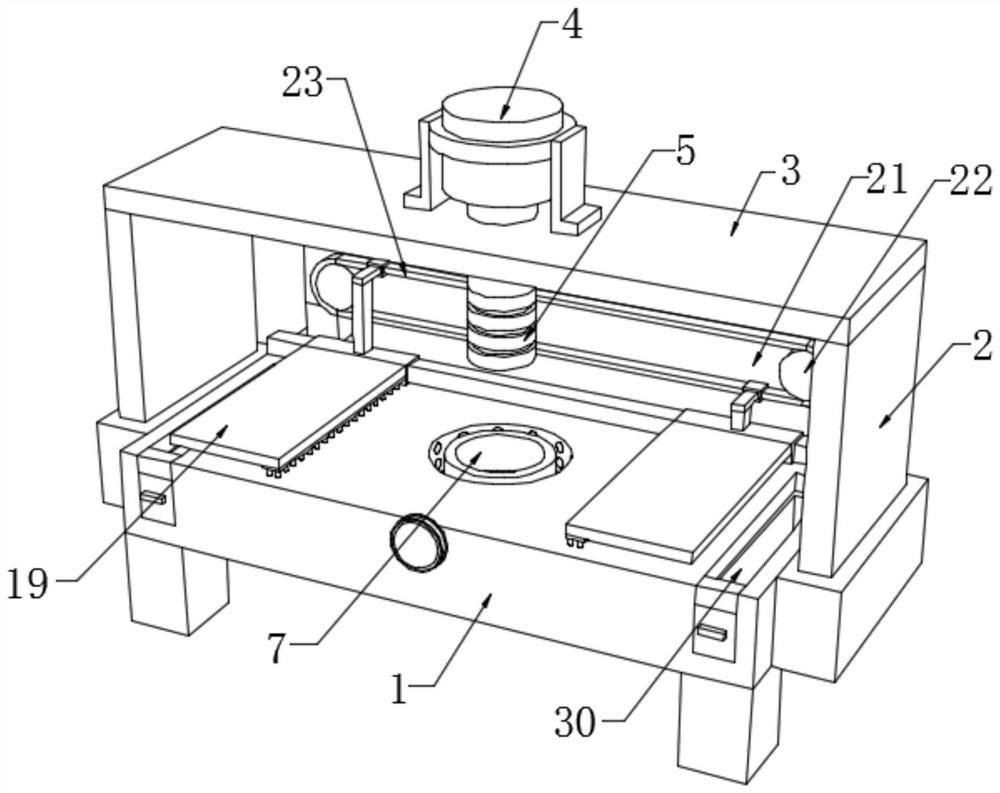
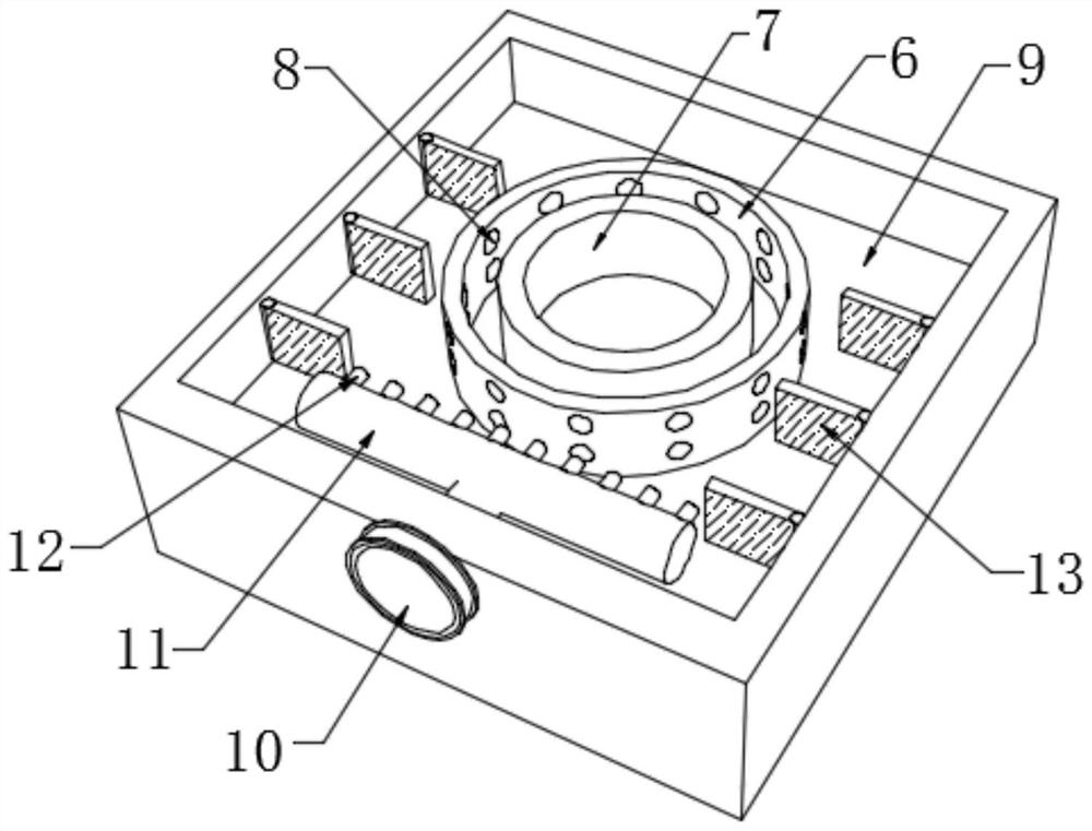
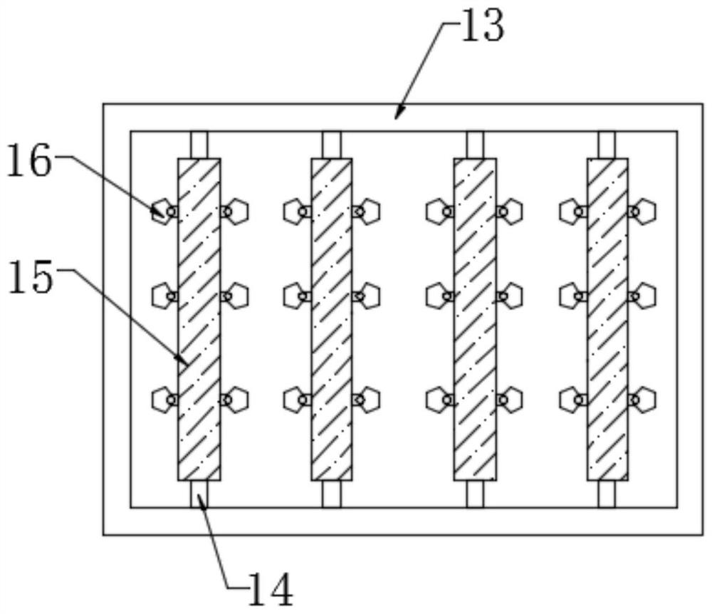
[0033] Such as Figure 1-3As shown, an insert fixed seat die with heat dissipation holes includes a work surface 1, a mounting frame 2, a top frame 3, an insert device body 4, a blade knife 5, a placement groove 6, a fixed seat die body 7, and a heat dissipation hole body 8. Operation slot 9, fan 10, diversion pipe 11, diversion pipe 12, wind deflector 13, rotating shaft 14, connecting cylinder 15, dispersion fan blade 16, sliding rod 17, first sleeve 18, baffle 19, Cleaning brush 20, mounting plate 21, connecting shaft 22, pulley 23, second sleeve 24, cross bar 25, vertical bar 26, mounting shaft 27, mounting hole 28, diversion groove 29, waste collection box 30, slider 31. Scraper 32, adjustment groove 33, handle 34, auxiliary shaft 35, crank handle 36 and support column 37, both sides of the work surface 1 are fixedly installed with mounting frames 2, and the tops of the two mounting frames 2 are fixedly mounted with top Frame 3, the middle part of the top frame 3 is fixed...
Embodiment 2
[0036] On the basis of Example 1, as figure 1 with Figure 4-8 As shown, the top of the worktable 1 is fixedly connected with a sliding rod 17, the length of the sliding rod 17 is consistent with the length of the worktable 1, and the outer wall of the sliding rod 17 is provided with two first sleeves 18, two first sleeves One side adjacent to the barrel 18 is provided with mounting holes 28, and the inner walls of the two mounting holes 28 are rotatably connected with mounting shafts 27, and one end of the two mounting shafts 27 is fixedly connected with a baffle plate 19, and the two baffle plates 19 are connected to each other. One end of the side is fixedly equipped with cleaning brushes 20, and the bottom ends of the two cleaning brushes 20 are all fitted with the top of the work surface 1, and the sliding rod 17, the first sleeve 18, the baffle plate 19, and the installation shaft 27 are arranged to Cooperating with the first sleeve 18, the baffle plate 19 is rotated th...
PUM
 Abstract
Description
Claims
Application Information
 - R&D
- Intellectual Property
- Life Sciences
- Materials
- Tech Scout
- Unparalleled Data Quality
- Higher Quality Content
- 60% Fewer Hallucinations
Browse by: Latest US Patents, China's latest patents, Technical Efficacy Thesaurus, Application Domain, Technology Topic, Popular Technical Reports.
© 2025 PatSnap. All rights reserved.Legal|Privacy policy|Modern Slavery Act Transparency Statement|Sitemap|About US| Contact US: help@patsnap.com


