
Electric spark punching rapid penetrating machining method and punching machine

A processing method and electric spark technology, applied in electric processing equipment, metal processing mechanical parts, metal processing equipment, etc., can solve the problem of inability to flush workpiece hole waste, electrode wire and workpiece unable to continue to discharge, and failure to meet processing requirements, etc. question

Inactive Publication Date: 2022-05-13
成都和鸿科技股份有限公司
View PDF16 Cites 0 Cited by
  • Summary
  • Abstract
  • Description
  • Claims
  • Application Information

AI Technical Summary

Problems solved by technology

In turn, the high-pressure water in the electrode wire flows out directly and cannot wash the waste in the workpiece hole
These wastes separate the wire electrode from the workpiece, making it impossible to continue the discharge between the wire electrode and the workpiece
This makes it impossible for the wire electrode to complete the machining of the last section of the workpiece hole
At the same time, if the electrode wire cannot finish punching for a long time and cannot continue to move forward, this may cause the electrode wire to contact the wall of the hole that has already been drilled, and then cause the wall of the hole that has already been punched to discharge with the electrode wire to make the hole diameter get bigger
In turn, the hole cannot meet the processing requirements

Method used


Image

  • Electric spark punching rapid penetrating machining method and punching machine
  • Electric spark punching rapid penetrating machining method and punching machine
  • Electric spark punching rapid penetrating machining method and punching machine

Examples


Embodiment

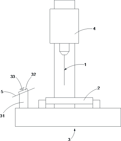
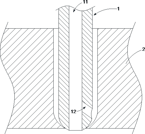
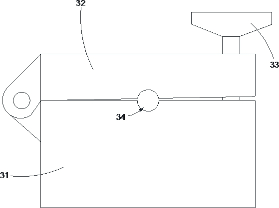
[0030] Such as Figure 1-Figure 3 As shown, the present invention provides a rapid penetration processing method for electric discharge drilling, which uses a punching machine to punch holes. The punching machine can be a common electric spark punching machine. The wire electrode 1 is installed in a punching machine, and the position of the wire electrode 1 is adjusted by the punching machine to punch a workpiece 2 . The electrode wire 1 is in the shape of a tube, and a flow hole 11 is arranged inside it along its length direction. The outer wall of the front end of the electrode wire 1 is provided with a guide hole 12 communicating with the flow hole 11 . The setting timing of the guide hole 12 is before the workpiece hole penetrates the workpiece 2 . Specifically, when the wire electrode 1 starts drilling and the hole reaches a certain depth, the wire electrode 1 is withdrawn from the workpiece hole and the diversion hole 12 is processed, and then the wire electrode 1 is ...


PUM


Abstract

The invention relates to the technical field of fine hole electric discharge machines, in particular to an electric spark punching rapid penetrating machining method and a punching machine, and the punching machine is adopted for punching. The electrode wire is installed on the perforating machine, and the position of the electrode wire is adjusted through the perforating machine so that the workpiece can be perforated. The electrode wire is tubular, and a circulation hole is formed in the electrode wire in the length direction. A flow guide hole communicated with the circulation hole is formed in the outer side wall of the front end of the electrode wire. The flow guide hole is formed before the workpiece hole penetrates through the workpiece. And a punching electrode wire is arranged on a fixed part of the punching machine. The punching electrode wire and the workpiece are connected to the same electrode. The electrode wire is provided with the flow guide hole, so that when the tip end of the electrode wire penetrates through the workpiece, deionized water jetted by the flow guide hole can continue to wash the hole wall, and then the electrode wire can well complete the remaining punching action.

Description

technical field [0001] The invention relates to the technical field of fine-hole electric discharge machines, in particular to an electric spark drilling fast penetration processing method and a punching machine. Background technique [0002] In machining, drilling is generally done with a drill bit. However, for extremely small apertures, the hole is generally drilled by electric spark drilling. For thinner workpieces, the wire electrode is easy to penetrate and punch to complete. For thicker workpieces, when the drilling depth reaches more than 10mm, the front end of the electrode wire will be tapered after a long period of consumption. This makes the tip of the electrode wire penetrate the workpiece, but its rear end still fails to penetrate the workpiece. At this time, the hole of the workpiece is also tapered. That is, the hole diameter of the portion where the tip of the wire electrode penetrates the workpiece is the same as the outer diameter of the tip of the wir...

Claims


Application Information

Patent Timeline
IPC IPC(8): B23H9/14B23H11/00B23Q11/00
CPCB23H9/14B23H11/00B23H11/003B23H11/006B23Q11/0042
Inventor 郑珂张爱民徐培江
Owner 成都和鸿科技股份有限公司
Learn More