
Disk-soldering device, system and method based on disc-shaped or QFP (Quad Flat Package) device

A packaged device, dish-shaped technology, applied in auxiliary devices, welding equipment, metal processing equipment, etc., can solve the damage of dish-shaped packaged devices and QFP packaged devices, the direction of hot air and the size of the heating point cannot be accurately and effectively controlled, damage, etc. question

Pending Publication Date: 2022-05-13
SHENZHEN ANEWBEST ELECTRONICS TECH
View PDF5 Cites 0 Cited by
  • Summary
  • Abstract
  • Description
  • Claims
  • Application Information

AI Technical Summary

Problems solved by technology

However, disc-shaped package devices and QFP package devices usually have poor heat resistance, and when the temperature reaches 85 0 When C and above, it will cause irreversible damage
[0004] When using a heat gun to heat the solder joints, the direction of the hot air and the size of the heating point cannot be accurately and effectively controlled, and the temperature is high during the heating process, which is likely to affect the disc package device and the QFP package device itself and cause irreversible damage risk
[0005] When the laser galvanometer is used to scan and desolder, the solder in the solder joints will produce reflection or diffuse reflection effect on the laser, and it is also easy to cause burns to the disc package device and QFP package device

Method used


Image

  • Disk-soldering device, system and method based on disc-shaped or QFP (Quad Flat Package) device

Examples


Embodiment Construction

[0022] The claims of the present invention will be further described in detail below in conjunction with specific embodiments and accompanying drawings. Apparently, the described embodiments are only some of the embodiments of the present invention, not all of them. Based on the embodiments of the present invention, all other embodiments obtained by persons of ordinary skill in the art without creative work also fall within the protection scope of the present invention.

[0023] It should be understood that, in the descriptions of the embodiments of the present invention, all directional terms, such as "up", "down", "left", "right", "front", "rear", etc. indicate the orientation or position The relationship is based on the orientation and positional relationship shown in the drawings or the conventional orientation or positional relationship of the product of the invention in use, which is only for the convenience of simplifying the description of the present invention, rather ...


PUM


Abstract

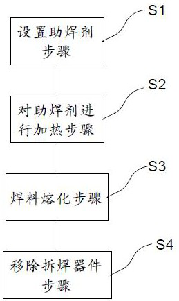
The method is suitable for the technical field of welding. The invention discloses a desoldering device, system and method based on a disc-shaped or QFP packaging device, the desoldering device based on the disc-shaped or QFP packaging device comprises a microwave heater for heating a welding spot solder with the surface coated with a soldering flux until the welding spot solder is molten, and the soldering flux can be heated by the microwave heater. And the boiling point is higher than the melting point of the welding spot solder. Due to the fact that the soldering flux contains components such as water molecules or hydrogen and oxygen atoms which can be heated by microwaves, the soldering flux on the surface of the soldering flux can be heated when the soldering flux is placed in the microwave heater with the specific wavelength, and when the boiling point of the soldering flux is higher than the melting point of the soldering flux, the soldering flux does not reach the boiling point when the soldering flux melts. And in the heating process of the microwaves, the temperature rise influence on the dish-shaped or QFP packaging device is avoided, the desoldering of the device by the microwaves is realized, and the influence of the temperature on the device during desoldering is reduced.

Description

technical field [0001] The invention relates to the technical field of electrical welding, in particular to a desoldering device, equipment and method for disc-shaped or QFP packaged devices. Background technique [0002] Disc packaged devices and QFP packaged devices play a pivotal role in the modern electronics industry. The cost of devices using these two packaging methods is high, and they often need to be desoldered from the substrate for recycling or reuse. [0003] Traditional desoldering methods include hot air guns, galvanometer scanning, etc., to heat the solder (also known as solder joint solder) on the PIN pins of disc-shaped packaged devices and QFP packaged devices to remelt the solder into a liquid state, and then remove the device from the substrate. to remove. However, disc-shaped package devices and QFP package devices usually have poor heat resistance, and when the temperature reaches 85 0 When it is C or above, it will be irreversibly damaged. [0004]...

Claims


Application Information

Patent Timeline
Patent Type & Authority Applications(China)
IPC IPC(8): B23K3/00B23K3/08
CPCB23K3/00B23K3/082
Inventor 周旋王海英檀正东杜君宽王海明黄艳玲
Owner SHENZHEN ANEWBEST ELECTRONICS TECH
Learn More