Automatic polishing machine for outer wall of metal pipe fitting

A technology for metal pipe fittings and polishing machines, which is applied in metal processing equipment, grinding/polishing equipment, grinding/polishing safety devices, etc., and can solve problems such as the generation of a large amount of metal powder, offset, and incomplete powder collection. Achieve the effect of reducing the content of metal powder, ensuring the quality of polishing, and collecting completely

Active Publication Date: 2022-05-13
江苏沂人智能制造科技有限公司
View PDF15 Cites 0 Cited by
  • Summary
  • Abstract
  • Description
  • Claims
  • Application Information

AI Technical Summary

Problems solved by technology

[0002] Pipe fittings are a general term for parts that play the roles of connection, control, direction change, diversion, sealing, support, etc. in the pipeline system. Existing pipe fittings are often divided into plastic pipe fittings, graphite pipe fittings and metal pipe fittings according to their materials. In the past, polishing machines were often used to polish the outer wall of metal pipe fittings, but the existing polishing machines often have certain deficiencies in polishing the surface of metal pipe fittings.
[0003] The existing metal pipe fittings still have the following problems in the polishing process: a: The existing circular metal pipe fittings often need to be manually pushed forward to move the metal pipe fittings forward during manual polishing, and the metal pipe fittings often move under the action of artificial thrust. Offset phenomenon will occur, which will affect the polishing effect of the metal pipe fitting surface; b: Existing metal pipe fittings will produce a large amount of metal powder chips during polishing. In some cases, metal powder chips are often adhered to the grinding belt, which will affect the subsequent polishing effect.

Method used


Image

  • Automatic polishing machine for outer wall of metal pipe fitting
  • Automatic polishing machine for outer wall of metal pipe fitting
  • Automatic polishing machine for outer wall of metal pipe fitting

Examples


Embodiment Construction

[0028] The technical solutions in the embodiments of the present invention will be clearly and completely described below with reference to the accompanying drawings in the embodiments of the present invention. Obviously, the described embodiments are only a part of the embodiments of the present invention, but not all of the embodiments. Based on the embodiments of the present invention, all other embodiments obtained by those of ordinary skill in the art without creative efforts shall fall within the protection scope of the present invention.

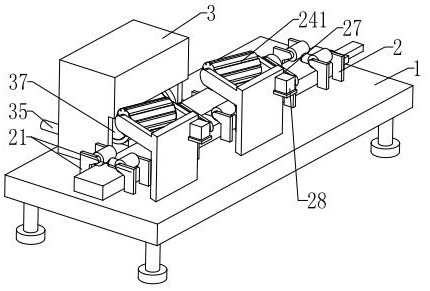
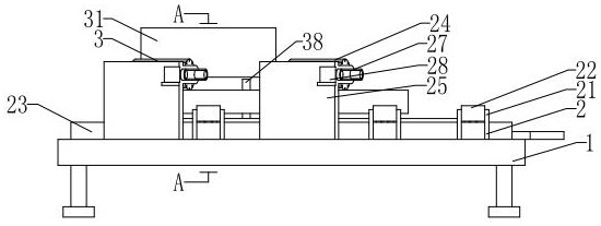
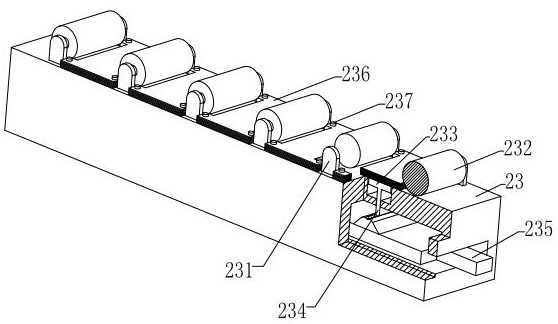
[0029] see Figure 1 to Figure 9 , an automatic polishing machine for the outer wall of metal pipe fittings, including a placement substrate 1, a traction unit 2, a polishing unit 3 and a chute E4, the upper end face of the placement substrate 1 is provided with a chute E4 at the rear end, and the upper end face of the placement substrate 1 is installed with traction Unit 2, a polishing unit 3 is provided above the pulling unit 2, and...


PUM


Abstract

The invention relates to the technical field of metal pipe fitting polishing and discloses a metal pipe fitting polishing device which comprises a containing base plate, a traction unit, a polishing unit and a sliding groove E. The sliding groove E is formed in the rear end of the upper end face of the containing base plate, the traction unit is installed on the upper end face of the containing base plate, and the polishing unit is arranged above the traction unit and installed on the containing base plate. The metal pipe fitting moves under the action of the traction unit, the surface of the metal pipe fitting is ground and polished through a grinding belt on the polishing unit, generated metal powder scraps are adsorbed to a collecting block under the action of magnetic force, the content of the metal powder scraps on the surface of the grinding belt is reduced, the grinding effect is prevented from being affected, and the production efficiency is improved. And meanwhile, along with continuous movement of the metal pipe fitting, the cleaning belt wipes the surface of the metal pipe fitting, the content of metal powder on the surface of the metal pipe fitting is reduced, and the metal powder on the cleaning belt and the grinding belt is scraped to a collecting frame through a scraping piece, so that the metal powder is collected more completely.

Description

technical field [0001] The invention relates to the technical field of metal pipe fitting polishing, in particular to an automatic polishing machine for the outer wall of a metal pipe fitting. Background technique [0002] Pipe fittings are the general term for the parts in the pipeline system that play the roles of connection, control, direction change, shunt, sealing, and support. Previously, polishing machines were often used to polish the outer walls of metal pipe fittings, but the existing polishing machines often had certain deficiencies when polishing the surfaces of metal pipe fittings. [0003] The existing metal pipe fittings also have the following problems when polishing: a: The existing circular metal pipe fittings often need to be manually pushed forward to move forward when the existing round metal pipe fittings are manually polished, and the metal pipe fittings often move under the action of artificial thrust. There will be offset phenomenon, which will affe...

Claims


Application Information

Patent Timeline
Patent Type & Authority Applications(China)
IPC IPC(8): B24B21/02B24B21/18B24B41/00B24B41/06B24B47/20B24B55/12B24B55/08B24B53/10
CPCB24B21/02B24B21/18B24B41/005B24B41/067B24B47/20B24B55/12B24B55/08B24B53/10Y02P70/10
Inventor 李玲
Owner 江苏沂人智能制造科技有限公司
Why Eureka
Try Eureka