
Sucking disc type bench drill

A suction cup type and bench drill technology, which is applied to portable drilling machines, drilling/drilling equipment, parts of boring machines/drilling machines, etc., can solve the problems of not satisfying the magnet base, etc., and achieve convenient use and operation, easy production and manufacturing, and reduce labor intensity effect

Inactive Publication Date: 2012-11-28
孙志强
View PDF0 Cites 3 Cited by
  • Summary
  • Abstract
  • Description
  • Claims
  • Application Information

AI Technical Summary

Problems solved by technology

For example, there is no workbench or board that is easy to connect and fix with bolts, and the magnetic condition that the magnet base is adsorbed and fixed is not satisfied. For example, when drilling holes on non-magnetic materials such as walls, floors, marble, granite, glass, etc., the electromagnet base of the drilling rig cannot Adhesive and fixed by magnetism

Method used


Image

  • Sucking disc type bench drill
  • Sucking disc type bench drill
  • Sucking disc type bench drill

Examples


Embodiment Construction

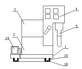
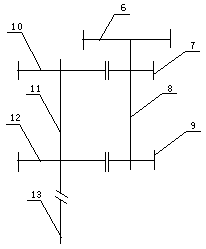
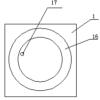
[0012] The support plate back side of the support is provided with a flange ring 15, and the section of the flange ring is trapezoidal. The sealing ring 16 is provided with a groove matching the flange ring, the sealing ring is connected on the flange ring through the groove, and the base plate is provided with a through hole 17, and the vacuum tube of the vacuum pump is connected to the through hole on the base plate. A fixed frame 2 is installed on the frame 1, and a motor 3, a transmission mechanism 4, a control circuit, an automatic feed mechanism and a stroke control switch are installed on the frame, and the rotor shaft of the motor is connected to the main shaft 13 through an automatic feed mechanism. , The travel control switch is connected to the control circuit. The input gear 6, the feed gear 9, and the transmission gear 7 are arranged on the spline shaft, the transmission gear and the spline shaft are slidably connected, and the feed gear is fixedly connected with ...


PUM


Abstract

The invention discloses a sucking disc type bench drill, belonging to the technical field of electric tools. A flange ring is arranged at the back of an engine base plate of an engine base, and a section of the flange ring is trapezoidal. A sealing ring is provided with a groove matched with the flange ring, the sealing ring is connected to the flange ring through the groove, a base plate is provided with a through hole, and a vacuum tube of a vacuum pump is connected to the through hole on the base plate. The engine base is fixedly connected with a frame, a motor, a transmission mechanism, a spindle, a control circuit, an automatic feeding mechanism and a travel control switch are arranged on the frame, a rotor shaft of the motor is in transmission connection with the spindle through the automatic feeding mechanism, the travel control switch is connected with a control circuit, a spline shaft is provided with an input gear, a feed gear and a transmission gear, and a thread shaft is provided with a differential gear and an output gear. The sucking disc type bench drill, provided by the invention, has the advantages of reasonable and compact structure, easiness in production and manufacturing, convenience for operation, and capability of automatically controlling the drilling depth and withdrawing a drill, reducing the labor intensity and improving the production efficiency and the processing quality of a product.

Description

technical field [0001] The invention relates to a bench drill structure in mechanical processing, in particular to a bench drill base structure, and belongs to the technical field of electric tools. Background technique [0002] Existing bench drills (drilling rigs) include machine bases, frames, motors, transmission mechanisms, spindles, control circuits, and manual feed mechanisms. , By manually turning the manual joystick to carry out drilling processing, the precision of the processed holes is not high, the labor intensity of the operators is high, and the work efficiency is low. Iron filings entangled with the drilling bit will easily cause the bit to be locked and affect the safety of the motor and the bit. When the bench drill is in use, the drilling machine needs to be stabilized and fixed. The way to fix the drilling machine is to fix the base of the drilling machine with the workbench by bolts, or to set an electromagnet on the drilling machine base. The existin...

Claims


Application Information

Patent Timeline
Patent Type & Authority Applications(China)
IPC IPC(8): B23B45/02B23B47/20B23B45/14
Inventor 孙志强
Owner 孙志强
Learn More