
Photovoltaic panel mounting mechanism for new energy automobile and mounting method of photovoltaic panel mounting mechanism

A new energy vehicle and installation mechanism technology, which is applied to the support structure of photovoltaic modules, separation methods, electric vehicles, etc., can solve the problems that affect the charging of new energy vehicles, the charging of new energy vehicles cannot be solved, and the damage of photovoltaic panels, etc., to achieve car washing Convenient, safe to use, and reduce the effect of sun and rain

Pending Publication Date: 2022-05-13
赵春丽
View PDF0 Cites 0 Cited by
  • Summary
  • Abstract
  • Description
  • Claims
  • Application Information

AI Technical Summary

Problems solved by technology

[0003] With the rapid development of modern new energy vehicles, people's demand for electric energy is also increasing. For some existing buildings, due to the lack of power equipment before, the charging of new energy vehicles cannot be solved in the later stage, which affects new energy vehicles. The existing photovoltaic panel canopy solves the problem of power supply for new energy vehicles, but in severe hail weather, because the photovoltaic panels are relatively thin, and there is no buffer shielding equipment above the photovoltaic panels of the existing photovoltaic panel canopy, It is easy to cause damage to photovoltaic panels and affect the charging of new energy vehicles

Method used


Image

  • Photovoltaic panel mounting mechanism for new energy automobile and mounting method of photovoltaic panel mounting mechanism
  • Photovoltaic panel mounting mechanism for new energy automobile and mounting method of photovoltaic panel mounting mechanism
  • Photovoltaic panel mounting mechanism for new energy automobile and mounting method of photovoltaic panel mounting mechanism

Examples


Embodiment Construction

[0029] The following will clearly and completely describe the technical solutions in the embodiments of the present invention with reference to the accompanying drawings in the embodiments of the present invention. Obviously, the described embodiments are only some, not all, embodiments of the present invention. Based on the embodiments of the present invention, all other embodiments obtained by persons of ordinary skill in the art without making creative efforts belong to the protection scope of the present invention.

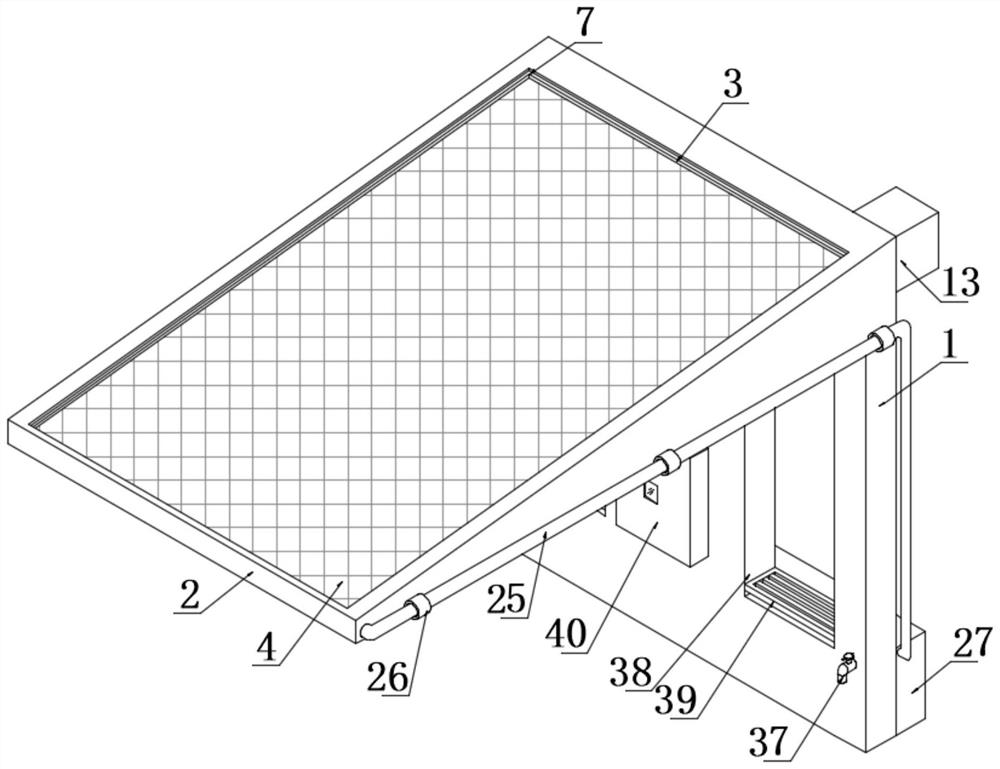
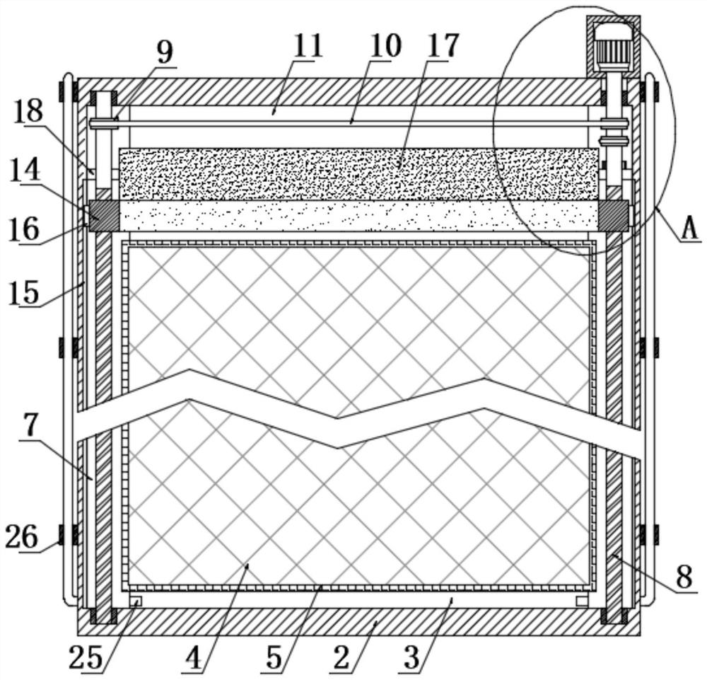
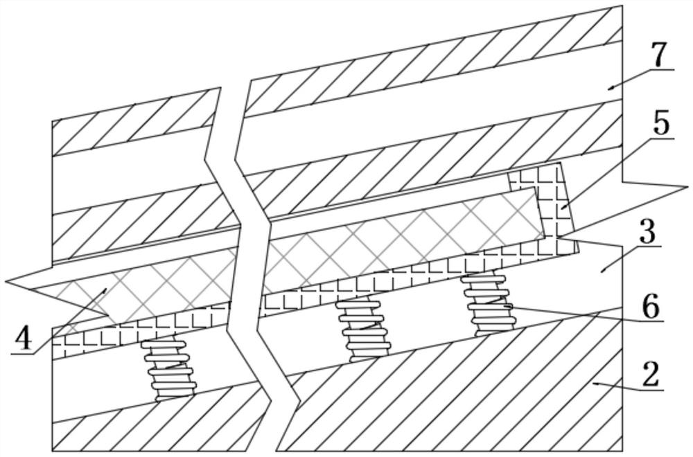
[0030] The present invention provides such as Figure 1-6A photovoltaic panel installation mechanism for new energy vehicles and its installation method are shown, including a support plate 1, the top of the support plate 1 is fixedly connected with a ceiling 2, and the top of the ceiling 2 is a slope structure, which is convenient for rainwater to slide down and photovoltaic panels. For the illumination of the module body 4, a loading slot 3 is provided on th...


PUM


Abstract

The invention discloses a photovoltaic panel mounting mechanism for a new energy automobile and a mounting method thereof.The photovoltaic panel mounting mechanism comprises a supporting plate, a ceiling is arranged at the top end of the supporting plate, a loading frame is arranged in an inner cavity of a loading groove, a photovoltaic panel assembly body is arranged in an inner cavity of the loading frame, and a plurality of compression springs are arranged at the bottom end of the loading frame at equal intervals; sliding grooves are formed in the two sides of the inner wall of the loading groove correspondingly, a connecting mechanism is arranged below the driving mechanism, sliding blocks are arranged on the outer walls of the two lead screws, a winding mechanism is arranged at one end of the protection piece, connecting pipes are arranged on the two sides of the ceiling correspondingly, and a collecting mechanism is arranged at the bottom of the supporting plate. The arrangement mode that the driving mechanism and the winding mechanism are matched is utilized, the photovoltaic panel assembly body can be protected through the connecting mechanism, damage to the photovoltaic panel assembly body can be reduced through a compression spring, the photovoltaic panel assembly body is safer to use, and the charging stability of the new energy automobile is improved.

Description

technical field [0001] The invention relates to the field of photovoltaic panels, in particular to a photovoltaic panel installation mechanism for new energy vehicles and an installation method thereof. Background technique [0002] Photovoltaic panel assembly is a power generation device that generates direct current when exposed to sunlight. It is composed of thin solid photovoltaic cells almost entirely made of semiconductor materials, referred to as photovoltaic panels. Photovoltaic panels can be made into different shapes, and components can be connected to generate more power. [0003] With the rapid development of modern new energy vehicles, people's demand for electric energy is also increasing. For some existing buildings, due to the lack of power equipment before, the charging of new energy vehicles cannot be solved in the later stage, which affects new energy vehicles. The existing photovoltaic panel canopy solves the problem of power supply for new energy vehicl...

Claims


Application Information

Patent Timeline
Patent Type & Authority Applications(China)
IPC IPC(8): B60L53/51B60S3/04H02S40/00H02S20/00H02S20/20B01D29/03
CPCB60L53/51B60S3/04H02S40/00H02S20/00H02S20/20B01D29/03Y02E10/50Y02T10/70Y02T10/7072Y02T90/12
Inventor 赵春丽
Owner 赵春丽
Learn More