
Novel batching tension control device of glass fiber weaving machine

A tension control, glass fiber loom technology, applied in the direction of winding strips, transportation and packaging, thin material handling, etc. Control, space saving, simple and compact connection structure

Pending Publication Date: 2022-05-13
青岛天一红旗特种织机科技有限公司
View PDF0 Cites 0 Cited by
  • Summary
  • Abstract
  • Description
  • Claims
  • Application Information

AI Technical Summary

Problems solved by technology

This tension control structure is used on glass fiber fabrics with a small weft density. Since the tension roller is on the upper part of the lower press roller, the cloth coming from the tension roller will pass through the outer surface of the lower press roller again, and the gap between the cloth and the tension roller It is easy to slip between them, making the cloth surface wrinkled and affecting the quality of the cloth surface

Method used


Image

  • Novel batching tension control device of glass fiber weaving machine
  • Novel batching tension control device of glass fiber weaving machine
  • Novel batching tension control device of glass fiber weaving machine

Examples


Embodiment Construction

[0025] It should be noted that in the description of the present invention, terms such as "upper", "lower", "left", "right", "front", "rear", etc. indicate the orientation or positional relationship based on the The orientation or positional relationship is just a relative term determined for the convenience of describing the structural relationship of the various components of the present invention, and does not specifically mean that any component in the present invention must have a specific orientation, be constructed and operated in a specific orientation, and cannot be understood as a reference to the present invention. limits.

[0026] In addition, descriptions such as "first", "second", "number one", and "number two" in the invention are only for the purpose of description, and do not specifically refer to the order or sequence, nor are they intended to limit the scope of this invention. Inventions are only used to distinguish components or operations described in the ...


PUM


Abstract

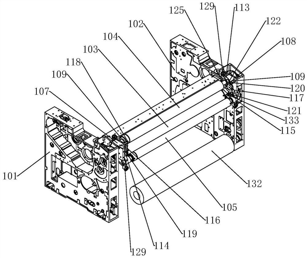
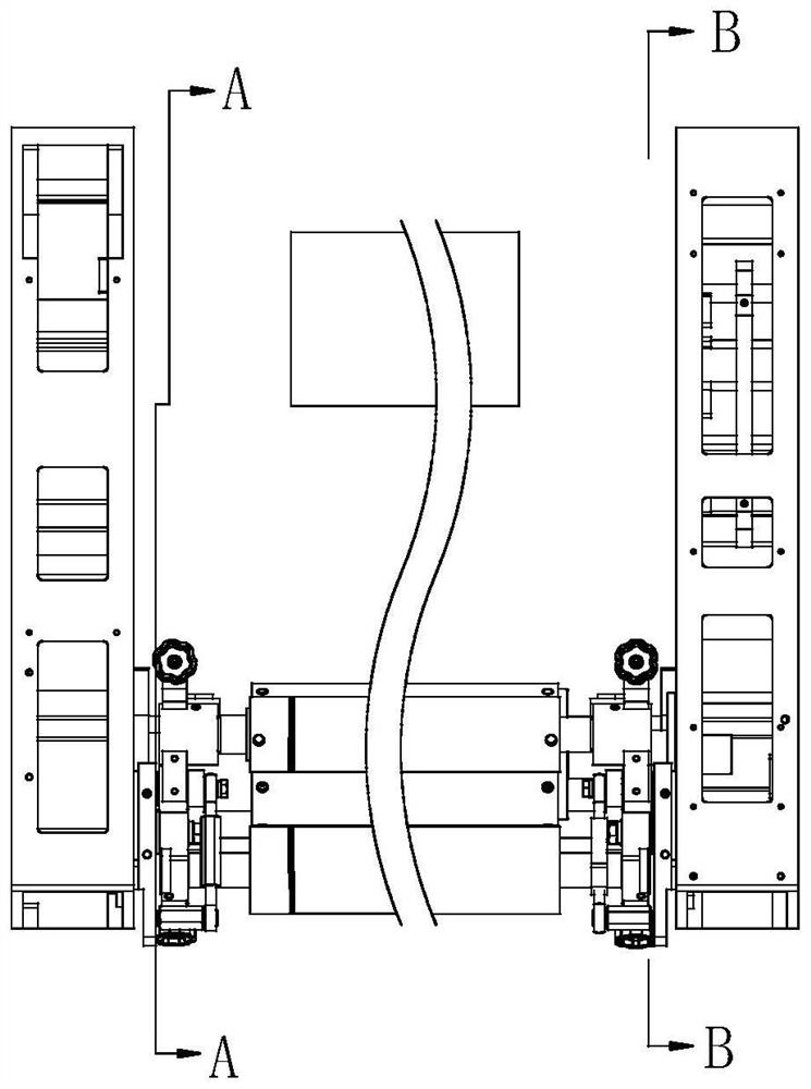
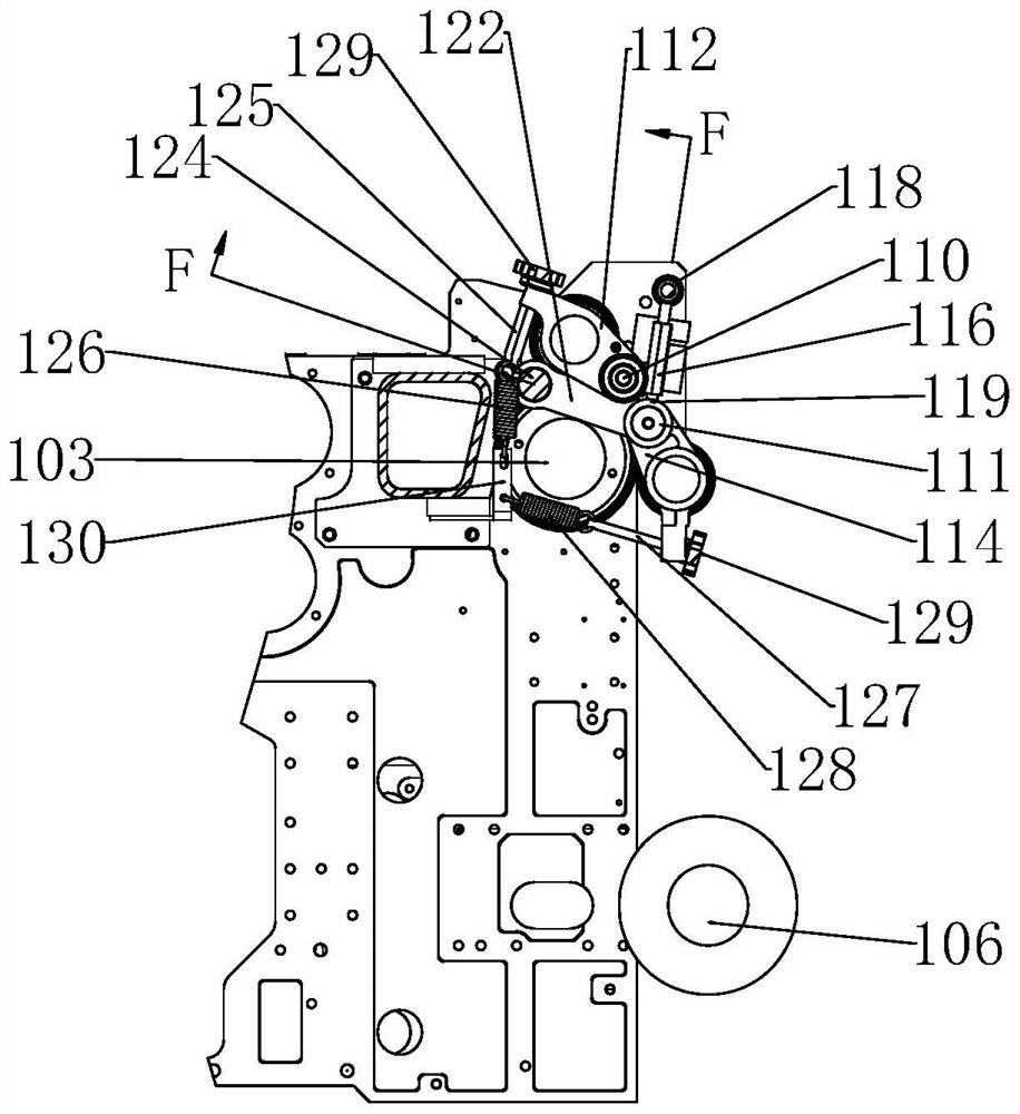
The invention discloses a novel cloth rolling tension control device of a glass fiber weaving machine. The novel cloth rolling tension control device comprises a rack, an upper cloth pressing roller, a winding roller and a tension roller. The rack comprises a left wallboard and a right wallboard, and a left fixing plate and a right fixing plate are correspondingly mounted on the inner side walls of the two wallboards; the winding roller is rotationally mounted between the left wallboard and the right wallboard through mounted fixed bearings at the two ends of the winding roller; the upper cloth pressing roller is rotationally mounted between the left fixing plate and the right fixing plate through upper cloth pressing roller arms at the two ends of the upper cloth pressing roller and located above the winding roller; the tension roller is rotationally mounted between the left and right fixing plates through tension roller arms at two ends of the tension roller and is positioned in front of and below the winding roller; meanwhile, a first tension connecting rod and a second tension connecting rod are further arranged on the two end sides of the tension roller and form stable triangular support with the corresponding lower connecting arms. An original lower cloth pressing roller and an original tension roller are combined into a whole, the structure is simpler and more compact, the space in a weaving machine is saved, the slippage phenomenon caused by insufficient pressing force of an independent tension roller and a cloth cover is effectively avoided, and the cloth cover wrinkling problem is solved.

Description

technical field [0001] The invention relates to the technical field of air-jet looms, in particular to a novel fabric tension control device for glass fiber looms. Background technique [0002] In the existing fiberglass loom, during the coiling process, the control of the cloth tension generally adopts four rollers of the upper pressing roller, the lower pressing roller, the tension roller and the take-up roller to control the entire cloth surface tension. This tension control structure is used on glass fiber fabrics with a small weft density. Since the tension roller is on the upper part of the lower press roller, the cloth coming from the tension roller will pass through the outer surface of the lower press roller again, and the gap between the cloth and the tension roller It is easy to slip between the two sides, which will make the cloth surface wrinkle and affect the quality of the cloth surface. Contents of the invention [0003] The purpose of the present inventio...

Claims


Application Information

Patent Timeline
Patent Type & Authority Applications(China)
IPC IPC(8): B65H18/02B65H18/14B65H23/26B65H19/30B65H20/02B65H26/04
CPCB65H18/028B65H18/14B65H23/26B65H19/30B65H20/02B65H26/04B65H2701/10
Inventor 吴海艳高玉刚邵星伟
Owner 青岛天一红旗特种织机科技有限公司
Learn More