Plugging prefabricated part and plugging method for assembled flue hanging hole

A technology for prefabricated components and flues, which is applied in the preparation of building components and building components on site, vertical pipes, etc. Slurry and other problems, to avoid the possibility of water leakage and slurry leakage, prevent horizontal smoke leakage and water leakage, and save labor costs.

Pending Publication Date: 2022-05-13
湖南三达数据科技有限公司
View PDF4 Cites 0 Cited by
  • Summary
  • Abstract
  • Description
  • Claims
  • Application Information

AI Technical Summary

Problems solved by technology

[0002] The traditional wind and flue installation is to reserve a hole on the floor that is larger than the outer cross-sectional size of the wind and flue. The reserved hole is sealed in the main construction or decoration stage. After the wind and flue are installed in place, the upper part of the hole is hung The formwork or formwork is set up by pulling and supporting, and the reserved opening is blocked by pouring concrete. This construction process is cumbersome due to the small operating space, and the joint between the formwork and the wind and flue is not tight, and it is easy to form construction joints. Common quality problems such as slurry leakage, resulting in poor quality of hole sealing and water seepage at the junction of wind, flue and floor. How to solve the above problems efficiently and simply is a technical problem that construction personnel urgently need to solve. For example, figure 1 As shown, currently when installing the upper and lower exhaust ducts, the industry adopts the method of installing the upper and lower exhaust ducts with rebar, but there is a lack of sealing of the upper exhaust ducts, which will cause water leakage during sealing phenomenon, and there is a gap between the upper and lower exhaust ducts, which may easily cause smoke leakage
[0003] At present, the existing method is to use two semicircular pipe hoops, and set a horizontal formwork connected with them as a shaping mold on the top of the pipe hoops, which effectively solves most of the shortcomings of commonly used wood boards and iron wires, but after practice The application and analysis of the existing patented technology also have the following defects: one is that the pipe collar and the pipe plugging formwork are integrated, and the finalized hanging form needs to be installed from the lower part of the completed concrete floor. The tightness of the bottom is all determined by the installation position of the pipe hoop, and the position of the pipe hoop cannot be adjusted conveniently and effectively, resulting in a certain theoretical gap between the suspended formwork and the concrete floor; the second is that the formwork and the floor are mostly made of sponge strips or rubber The strips need to be installed twice, and the sponge strips or rubber strips are mostly consumed at one time, the turnover rate is low, waste and garbage pollute the environment; the third hanging formwork is installed close to the lower part of the floor and the root of the pipe, lacking operating space, and inconvenient for personnel to operate

Method used


Image

  • Plugging prefabricated part and plugging method for assembled flue hanging hole
  • Plugging prefabricated part and plugging method for assembled flue hanging hole
  • Plugging prefabricated part and plugging method for assembled flue hanging hole

Examples


Embodiment 1

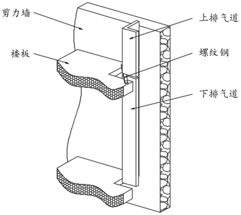
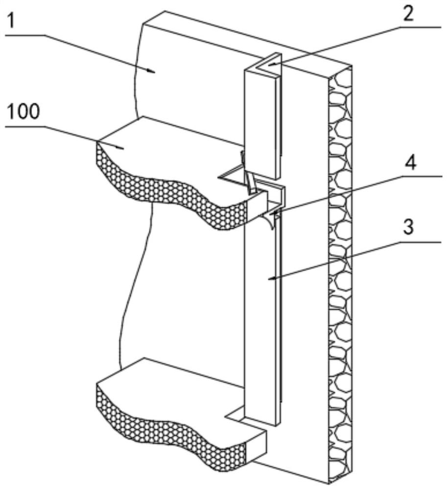
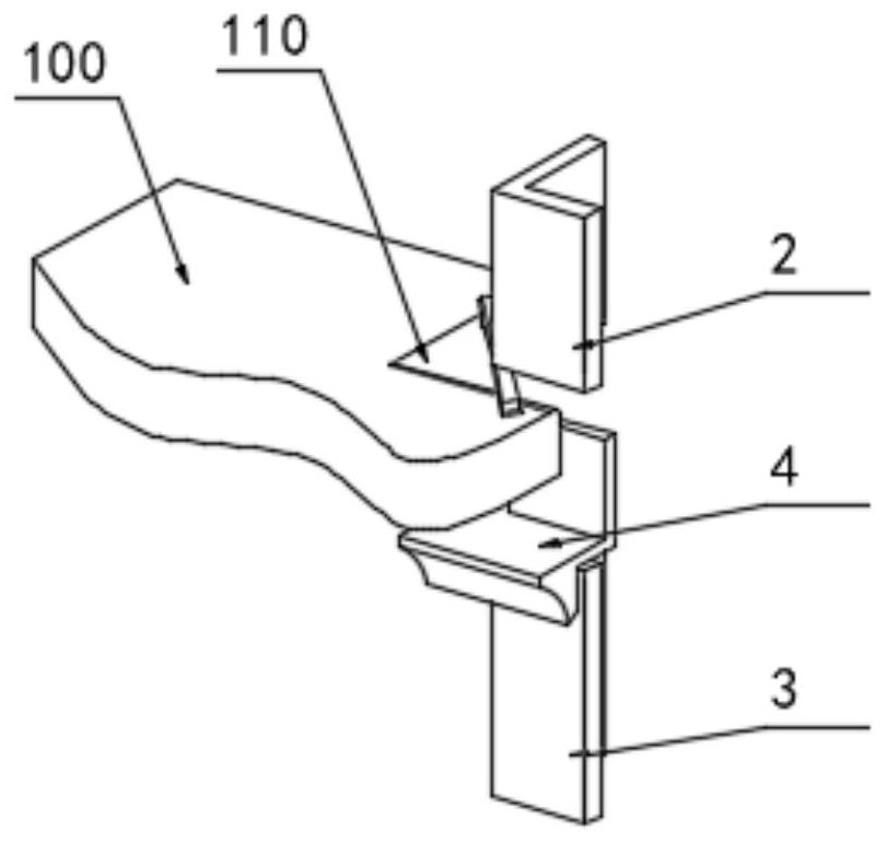
[0031] see Figure 2-Figure 7 As shown, a prefabricated component for assembling flue hanging hole sealing includes two vertically connected walls 1, and the wall surface of the wall 1 is fixedly connected with a plurality of floor slabs 100, and the surface of the floor slabs 100 is close to two adjacent walls. 1 is provided with a hole 110, the inside of the hole 110 is provided with an upper exhaust flue 2, and the lower exhaust flue 3 is arranged below the upper exhaust flue 2, and the upper exhaust flue 2 and the lower exhaust flue The junction of the road 3 is fitted with a prefabricated component block 4, the prefabricated component block 4 is installed in the hole 110 provided on the floor 100, the prefabricated component block 4 includes a horizontal template 400 used in conjunction with the bottom surface of the hole 110, and the prefabricated component block 4 also includes The upper fastener 410 is socketed with the inner wall of the upper exhaust flue 2 and the lo...

Embodiment 2

[0038] see Figure 6-Figure 7As shown, below the opening 110, there is also an anti-leakage sealing mechanism 5 that is attached to the bottom of the prefabricated component block 4. The anti-leakage sealing mechanism 5 includes an anti-seepage plate 500 that is attached to the bottom of the floor 100 and the fillet 440, and prevents leakage. The bottom end of seepage plate 500 is hinged with telescopic ejector rod 510, and the bottom end of telescopic ejector rod 510 is movably connected with anti-skid reinforcement seat 520. The connected telescopic rod, the telescopic rod and the sleeve rod move up and down through the piston push plate.

[0039] In order to prevent the possibility of seepage, when the gap of the hole 110 is too large, an anti-seepage board 500 is pasted under the hole 110, and the design height of the telescopic ejector rod 510 is greater than the height between two adjacent floors 100. The length of the telescopic push rod 510 and the sum of the lengths ...


PUM


Abstract

The invention discloses an assembly flue hanging hole plugging prefabricated part and a plugging method, and particularly relates to the technical field of flue hanging hole plugging, the assembly flue hanging hole plugging prefabricated part comprises two walls which are vertically connected, the wall surfaces of the walls are fixedly connected with a plurality of floors, holes are formed in the positions, close to the two adjacent walls, of the surfaces of the floors, and the holes are communicated with the walls. An upper exhaust flue is arranged in the hole, a lower exhaust flue is arranged below the upper exhaust flue, and a prefabricated part block is arranged at the joint of the upper exhaust flue and the lower exhaust flue in a sleeving mode. The prefabricated part block, the upper exhaust flue and the lower exhaust flue are installed at the same time, sleeving of the upper exhaust flue and the lower exhaust flue is achieved, meanwhile, fine aggregate concrete borne at a hole is poured and tamped through the horizontal formwork, the problems of formwork erecting, smoke leakage, water leakage and the like are solved, mortar permeates into gaps between the prefabricated part block and the upper exhaust flue and between the prefabricated part block and the lower exhaust flue, and the construction efficiency is improved. Horizontal smoke leakage and water leakage are prevented, and construction steps are simplified.

Description

technical field [0001] The invention relates to the technical field of flue hanging hole sealing, in particular to a prefabricated component for assembling flue hanging hole sealing and a sealing method. Background technique [0002] The traditional wind and flue installation is to reserve a hole on the floor that is larger than the outer cross-sectional size of the wind and flue. The reserved hole is sealed in the main construction or decoration stage. After the wind and flue are installed in place, the upper part of the hole is hung The formwork or formwork is set up by pulling and supporting, and the reserved opening is blocked by pouring concrete. This construction process is cumbersome due to the small operating space, and the joint between the formwork and the wind and flue is not tight, and it is easy to form construction joints. Common quality problems such as slurry leakage, resulting in poor quality of hole sealing and water seepage at the junction of wind, flue an...

Claims


Application Information

Patent Timeline
Patent Type & Authority Applications(China)
IPC IPC(8): E04F17/02E04G13/00E04G17/00
CPCE04F17/02E04G13/00E04G17/00E04F17/023E04G17/005
Inventor 段瀛段卜方
Owner 湖南三达数据科技有限公司
Why Eureka
Try Eureka