Eureka AIR delivers breakthrough ideas for toughest innovation challenges, trusted by R&D personnel around the world.

Experimental device and method for grouting and filling magnetic slurry fractures

An experimental device and crack technology, which is applied in the field of rock crack experiments, can solve the problems of lack of test equipment, etc., and achieve the effects of reducing costs, improving fluidity, and ensuring integrity

Pending Publication Date: 2022-05-13
CHINA THREE GORGES UNIV
View PDF0 Cites 4 Cited by
  • Summary
  • Abstract
  • Description
  • Claims
  • Application Information

AI Technical Summary

Problems solved by technology

Due to the limitations of test conditions, especially in the aspects of confining pressure loading, controllable dislocation of fractures, penetration sealing means, and realization of visualization, there are still limitations in domestic research on rock fracture grouting diffusion tests and test methods under complex conditions. Relevant test equipment is still relatively lacking

Method used


Image

  • Experimental device and method for grouting and filling magnetic slurry fractures
  • Experimental device and method for grouting and filling magnetic slurry fractures
  • Experimental device and method for grouting and filling magnetic slurry fractures

Examples


Embodiment 1

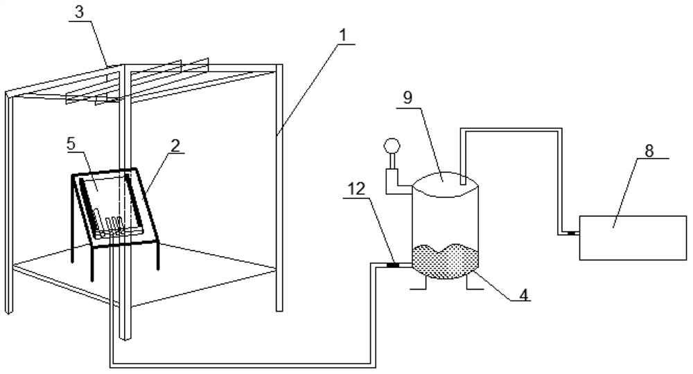
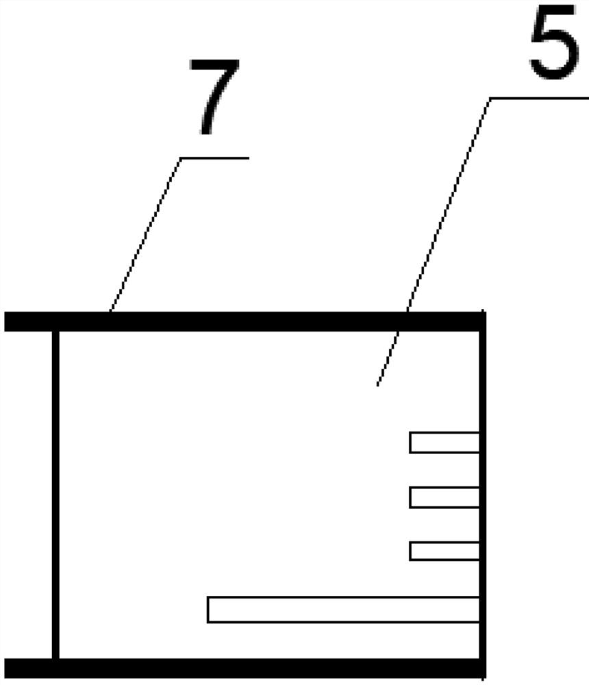
[0040] see Figure 1-3, an experimental device for magnetic slurry fissure grouting and filling, which includes a steel truss 1, and a fissure seepage visualization device 5 and a camera to be tested are mounted on the steel truss 1, and the fissure seepage visualization device 5 passes through grouting The tube is connected to the bottom grout outlet of the multifunctional pressure grouting tank 9 , and the top of the multifunctional pressure grouting tank 9 is connected with a pressure tube, and the pressure tube is in communication with the air pump 8 . Through the above experimental device, the flow track and filling area law of magnetic grout under different grouting pressures can be established, and the radial diffusion model of grouting grouting in cracks can be established; the grouting ratio parameters can be provided for different forms of cracking grouting repair projects, and the realization of Better filling of the inside of the crack, ensuring the quality of the ...

Embodiment 2

[0050] The experimental method of grouting and filling magnetic slurry cracks by using the experimental device comprises the following steps:

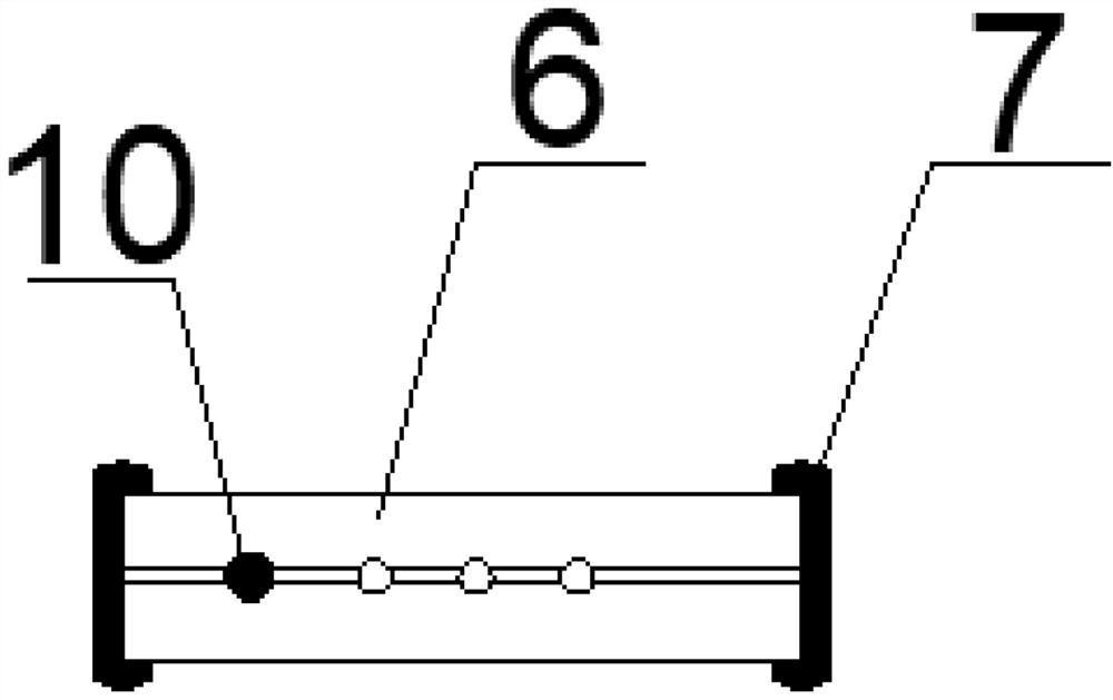
[0051] Step1. Material preparation: steel truss 1, base 2, camera holder 3, magnetic slurry 4, fissure seepage visualization device 5, acrylic plate 6, rubber sealing strip 7, air pump 8, multi-functional pressure grouting tank 9, magnetic Rod 10, video camera, grouting control valve 12;

[0052] Step2: Make magnetic slurry 4: Determine the weight required for cement, water, water-based epoxy resin, magnetic powder and asphalt materials according to the ratio of magnetic slurry 4, use an electronic balance to weigh the corresponding weight materials and put them into the steel cylinder, then Thoroughly stir after turning on the power of the stirrer;

[0053] Step3: Install the fissure seepage visualization device 5: Place the magnetic rod 10 in the reserved magnetic rod hole inside the acrylic plate 6 and place two silicone gaskets on...


PUM


Abstract

The invention provides an experimental device and method for magnetic slurry crack grouting and filling, the experimental device comprises a steel truss, a crack seepage visualization device to be experimented and a camera are carried on the steel truss, the crack seepage visualization device is connected with a bottom slurry outlet of a multifunctional pressure grouting tank through a grouting pipe, and the camera is connected with the multifunctional pressure grouting tank. The top of the multifunctional pressure grouting tank communicates with a pressure pipe, and the pressure pipe communicates with an air pump. Establishing a flow track and a filling area rule of magnetic grout under the action of different grouting pressures, and establishing a crack grout grouting radial diffusion model; slurry matching parameters are provided for different types of crack grouting repair projects, better filling of the interior of the crack is achieved, and the cost is reduced while the repair quality is guaranteed.

Description

technical field [0001] The invention belongs to the technical field of rock crack experiments, in particular to an experimental device and method for grouting and filling magnetic slurry cracks. Background technique [0002] In recent years, with the continuous development of domestic foundation engineering, the construction scale of various tunnels (caves) has also been continuously expanded. Sex plays an important role. On the one hand, cracks in rock mass are one of the important causes of water damage in underground engineering. On the other hand, the existence of cracks also greatly reduces the strength of rock mass. Filling the cracks by grouting can not only effectively prevent water damage in the project, but also improve the integrity of the surrounding rock, and the reinforcement effect on the broken rock mass is very obvious. During the grouting process, the diffusion law of the grout in the crack has a decisive and important influence on the effect of water blo...

Claims


Application Information

Patent Timeline
Patent Type & Authority Applications(China)
IPC IPC(8): G01N13/04G01N15/08H04N5/225
CPCG01N13/04G01N15/082G01N2013/003H04N23/57
Inventor 刘杰莫承林冯靖童石谦蔡显灿黎照付馨予郭建祥胡源聂弘赵凯强石磊王昊
Owner CHINA THREE GORGES UNIV
Why Eureka
Eureka Blog
Learn More