Chitosan oligosaccharide detection device with metal detection function
A metal detection and detection device technology, applied in measuring devices, testing food, material inspection products, etc., can solve the problems of low efficiency and troublesome determination of exceeding the standard position, and achieve the effect of reducing manual operation and ensuring accuracy
- Summary
- Abstract
- Description
- Claims
- Application Information
AI Technical Summary
Problems solved by technology
Method used
Image
Examples
Embodiment 1
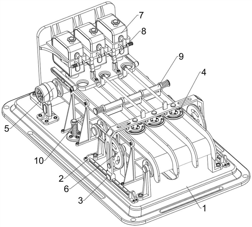
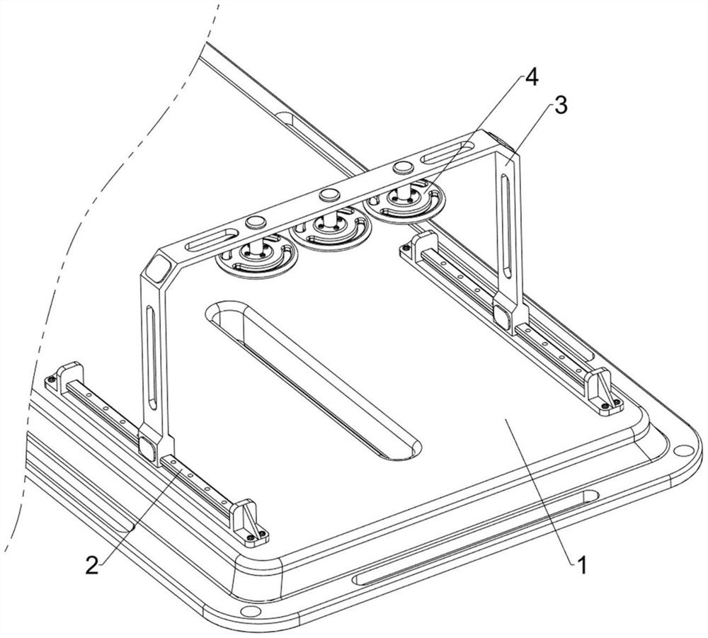
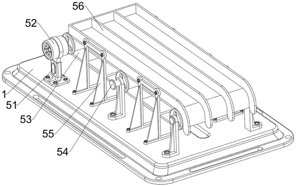
[0034] A chitosan oligosaccharide detection device with metal detection function, such as Figure 1 to Figure 4 As shown, it includes a base 1, a guide seat 2, a sliding frame 3, a metal detection sensor 4, an automatic feeding mechanism 5, and a reciprocating detection mechanism 6. The front side of the top of the base 1 is symmetrically provided with a guide seat 2. Slidingly connected with a sliding frame 3, there are three metal detection sensors 4 on the top of the sliding frame 3, and the metal detection sensors 4 are used to detect whether the metal exceeds the standard. The top of the base 1 is equipped with an automatic feeding mechanism 5, and there are 5 pairs of automatic feeding mechanisms. The powder is conveyed and loaded, and the detection is coordinated. The sliding frame 3 is provided with a reciprocating detection mechanism 6 .
[0035] The automatic feeding mechanism 5 includes a mounting seat 51, a servo motor 52, a first belt 53, a rotating shaft 54, a su...
Embodiment 2
[0039] On the basis of Example 1, such as figure 1 , Figure 5 , Image 6 with Figure 10As shown, an intermittent feeding mechanism 7 is also included, and the intermittent feeding mechanism 7 automatically feeds the powder intermittently. The intermittent feeding mechanism 7 includes a mounting table 71, a placement tank 72, a guide groove plate 73, and a first return spring 74 , blockage plate 75, contact plate 76 and push rod 77, base 1 top rear side is provided with installation table 71, and installation table 71 upper front side is placed with 3 placement tanks 72, divider plate 56 rear portion left and right sides are all provided with The guide groove plate 73 is slidably connected with a blockage plate 75 between the guide groove plate 73, and the blockage plate 75 moves left and right to continuously block the placement tank 72, and the blockage plate 75 is connected with a first reset between the guide groove plate 73 inner rear side. Spring 74, blocking plate 7...
Embodiment 3
[0043] On the basis of Example 2, such as figure 1 , Figure 7 , Figure 8 , Figure 9 , Figure 11 with Figure 12 As shown, a knocking mechanism 8 is also included, and the knocking mechanism 8 knocks the placement tank 72 to assist the powder to flow out. The knocking mechanism 8 includes a mounting bracket 81, a knocking column 82, a first torsion spring 83, a contact rod 84, guide frame 85, second back-moving spring 86 and wedge-shaped block 87, mounting table 71 top front side is provided with 3 mounting brackets 81, is connected with percussion column 82 in rotation between mounting bracket 81, percussion column 82 and the outside The first torsion spring 83 is connected between the two mounting brackets 81, the contact rod 84 is symmetrically arranged on the knocking column 82, and the guide frame 85 is symmetrically arranged on the front side of the top of the blocking plate 75, and the guide frame 85 is passed through The second return spring 86 is slidably conn...
PUM
 Abstract
Description
Claims
Application Information
 - R&D
- Intellectual Property
- Life Sciences
- Materials
- Tech Scout
- Unparalleled Data Quality
- Higher Quality Content
- 60% Fewer Hallucinations
Browse by: Latest US Patents, China's latest patents, Technical Efficacy Thesaurus, Application Domain, Technology Topic, Popular Technical Reports.
© 2025 PatSnap. All rights reserved.Legal|Privacy policy|Modern Slavery Act Transparency Statement|Sitemap|About US| Contact US: help@patsnap.com


