
Intelligent pressure relief equipment for box-type substation

A box-type substation, intelligent technology, applied in distribution substation, substation/switchgear cooling/ventilation, substation/switch layout details, etc., can solve the problems of interval equipment damage, box bursting, high voltage, etc., and achieve good waterproof Effects of dust prevention and increased pressure relief capability

Inactive Publication Date: 2022-05-13
柴祥杰
View PDF0 Cites 0 Cited by
  • Summary
  • Abstract
  • Description
  • Claims
  • Application Information

AI Technical Summary

Problems solved by technology

[0002] Box-type substation is a kind of high-voltage switchgear, distribution transformer and low-voltage power distribution device. At present, the box-type substation on the market lacks a pressure relief mechanism. The internal air pressure of the transformer box is too high, which will cause damage to other spacers in the box or bursting of the box, and the safety performance is poor
[0003] In order to solve the above problems, we provide an intelligent pressure relief device for box-type substations, which can automatically release pressure when the internal pressure of box-type substations is too high to avoid explosion accidents in substations, good waterproof and dustproof, and avoid high-pressure pressure relief When the pressure relief channel is quickly closed, resulting in high pressure inside the box-type substation again

Method used


Image

  • Intelligent pressure relief equipment for box-type substation
  • Intelligent pressure relief equipment for box-type substation
  • Intelligent pressure relief equipment for box-type substation

Examples


Embodiment 1

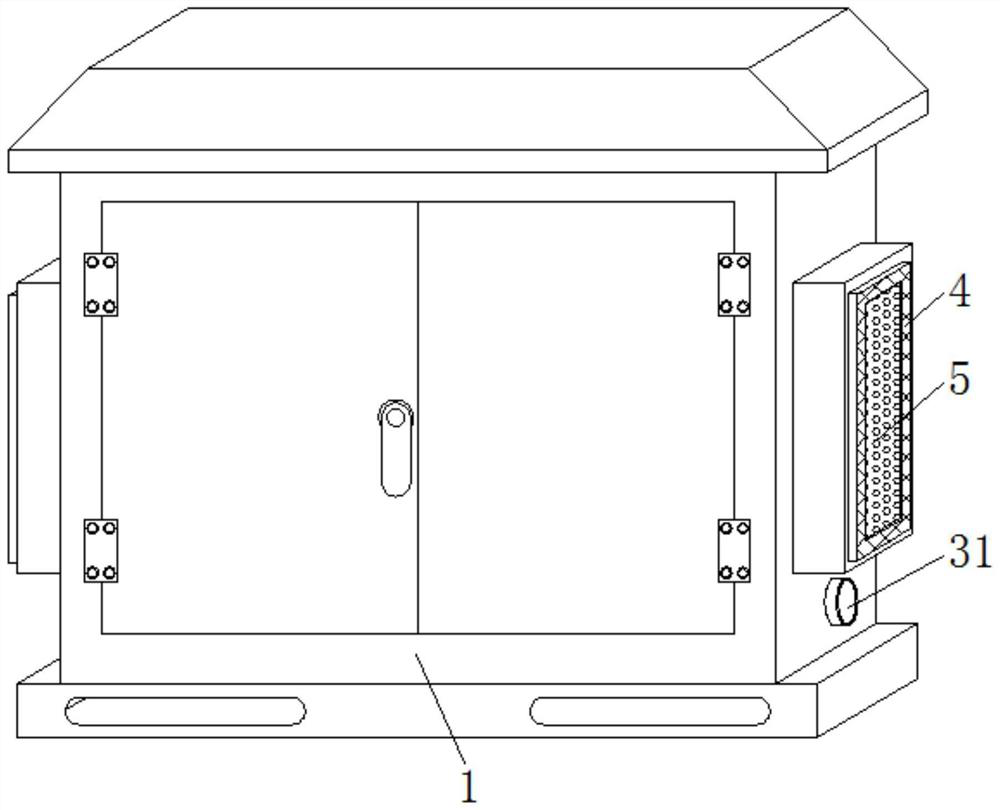
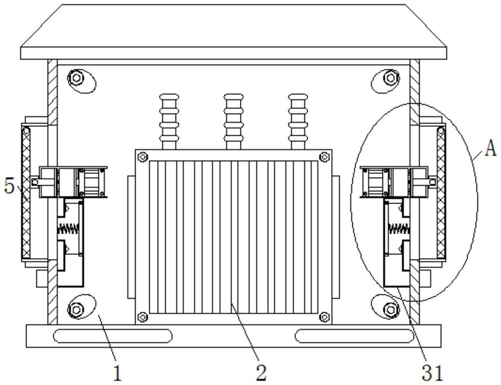
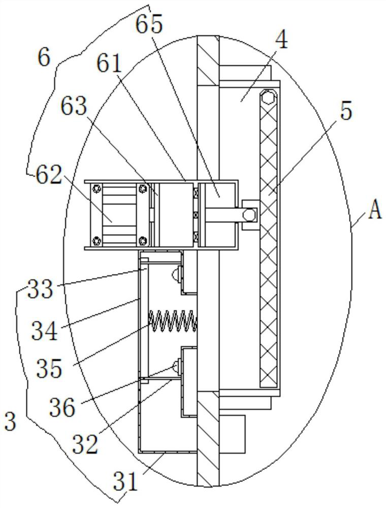
[0026] see Figure 1-4 , an intelligent pressure relief device for box-type substations, including a conventional pressure relief assembly 3, a pressure relief pipe 31 is arranged inside the conventional pressure relief assembly 3, the pressure relief pipe 31 is an L-shaped structure, and the bottom of the right side is in the Below the heat dissipation window 4, the top inside the pressure relief pipe 31 is welded with a fixed rod 32, and the outer wall of the fixed rod 32 is slidably connected with a gray plate 33, and the top of the left side of the pressure relief pipe 31 is provided with a pressure relief port 34, and the gray plate 33 is blocked on the right side of the pressure relief port 34, and the area of ​​the gray retaining plate 33 is greater than the area inside the pressure relief port 34, and the right side of the gray retaining plate 33 is fixedly connected with a supporting spring 35, and the supporting spring 35 is far away from the gray retaining plate 33. ...

Embodiment 2

[0030] see Figure 2-5 , an intelligent pressure relief device for box-type substations, including a high-pressure pressure relief assembly 6, a fixed groove 61 is arranged inside the high-pressure pressure relief assembly 6, and a telescopic cylinder 62 is fixedly connected to the left side of the fixed groove 61, and the telescopic cylinder The right side of 62 is fixedly connected with the first sealing plate 63, the outer wall on the right side of the first sealing plate 63 is slidingly connected with the first hydraulic groove 64, the inside of the fixed groove 61 right side is provided with the second hydraulic groove 65, the second hydraulic groove The inside of 65 is slidably connected with a second sealing plate 66, the right side of the second sealing plate 66 is welded with a push rod 67, the right side of the push rod 67 is riveted to the left side of the cooling net 5, and the right side of the first hydraulic tank 64 is set There is a one-way oil outlet valve 68,...

Embodiment 3

[0035] see Figure 1-5, an intelligent pressure relief device for box-type substations, including a conventional pressure relief assembly 3, a pressure relief pipe 31 is arranged inside the conventional pressure relief assembly 3, the pressure relief pipe 31 is an L-shaped structure, and the bottom of the right side is in the Below the heat dissipation window 4, the top inside the pressure relief pipe 31 is welded with a fixed rod 32, and the outer wall of the fixed rod 32 is slidably connected with a gray plate 33, and the top of the left side of the pressure relief pipe 31 is provided with a pressure relief port 34, and the gray plate 33 is blocked on the right side of the pressure relief port 34, and the area of ​​the gray retaining plate 33 is greater than the area inside the pressure relief port 34, and the right side of the gray retaining plate 33 is fixedly connected with a supporting spring 35, and the supporting spring 35 is far away from the gray retaining plate 33. ...


PUM


Abstract

The invention provides intelligent pressure relief equipment for a box-type substation, and relates to the technical field of box-type substations. The intelligent pressure relief equipment for the box-type substation comprises a conventional pressure relief assembly, a pressure relief pipe is arranged in the conventional pressure relief assembly, a fixing rod is welded to the top of the interior of the pressure relief pipe, and the outer wall of the fixing rod is slidably connected with a dust blocking plate. And when the air pressure in the box body is continuously increased, the heat dissipation net can deflect rightwards in the heat dissipation window, so that the effect of automatically releasing the pressure to avoid the explosion accident of the transformer substation when the air pressure in the box-type transformer substation is too high is achieved. And when the air pressure in the box body gradually recovers, a time delay effect can be achieved when hydraulic oil in the second hydraulic groove enters the first hydraulic groove, so that the heat dissipation net is slowly reset to the interior of the heat dissipation window, and the situation that high pressure occurs in the box-type substation again due to the fact that the pressure relief channel is rapidly closed during high-pressure pressure relief is avoided.

Description

technical field [0001] The invention relates to the technical field of box-type substations, in particular to an intelligent pressure relief device for box-type substations. Background technique [0002] Box-type substation is a kind of high-voltage switchgear, distribution transformer and low-voltage power distribution device. At present, the box-type substation on the market lacks a pressure relief mechanism. The air pressure inside the transformer box is too high, which will cause damage to other spacers in the box or bursting of the box, and the safety performance is poor. [0003] In order to solve the above problems, we provide an intelligent pressure relief device for box-type substations, which can automatically release pressure when the internal pressure of box-type substations is too high to avoid explosion accidents in substations, good waterproof and dustproof, and avoid high-pressure pressure relief At this time, the pressure relief channel is quickly closed, r...

Claims


Application Information

Patent Timeline
IPC IPC(8): H02B13/025H02B1/28H02B1/56H02B1/46H02B1/48H02B7/06
CPCH02B13/025H02B1/28H02B1/565H02B1/46H02B1/48H02B7/06
Inventor 柴祥杰朱成强
Owner 柴祥杰
Learn More