Clamping device for antenna

A clamping device and antenna technology, which is applied in the direction of antenna support/installation device, antenna, antenna parts, etc., can solve the problem of heavy weight of the clamping device for antenna, reduce labor force, increase the freedom of setting, and improve the setting sexual effect

Pending Publication Date: 2022-05-13
KMW INC
View PDF0 Cites 0 Cited by
  • Summary
  • Abstract
  • Description
  • Claims
  • Application Information

AI Technical Summary

Problems solved by technology

[0007] Even for the antenna equipment manufactured due to the necessity of the above-mentioned compact and miniaturized design, due to its own weight and the weight of the antenna clamping device used to install and fix the antenna equipment, the weight is relatively large. Therefore, when the antenna is installed on the pole A lot of manpower is required to install or adjust the directivity of the installed antenna equipment

Method used


Image

  • Clamping device for antenna
  • Clamping device for antenna
  • Clamping device for antenna

Examples


Embodiment Construction

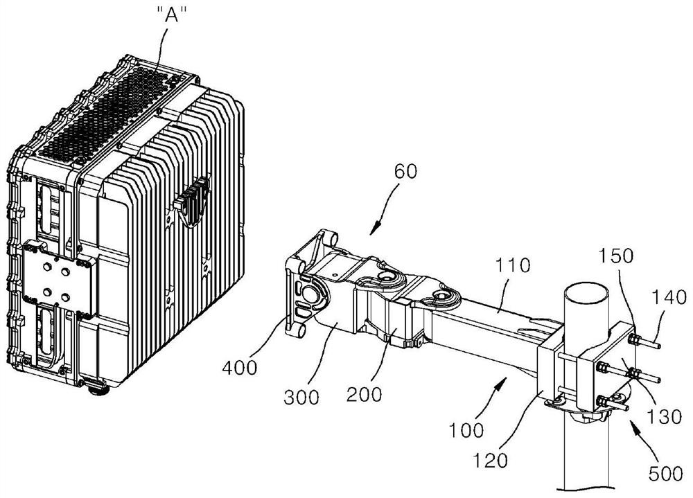
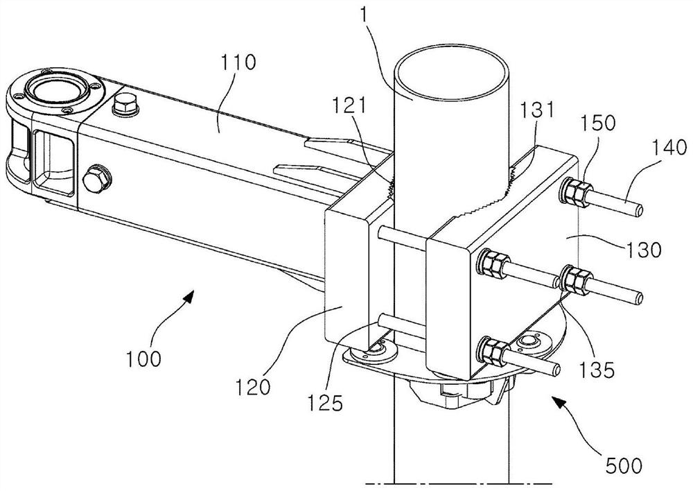
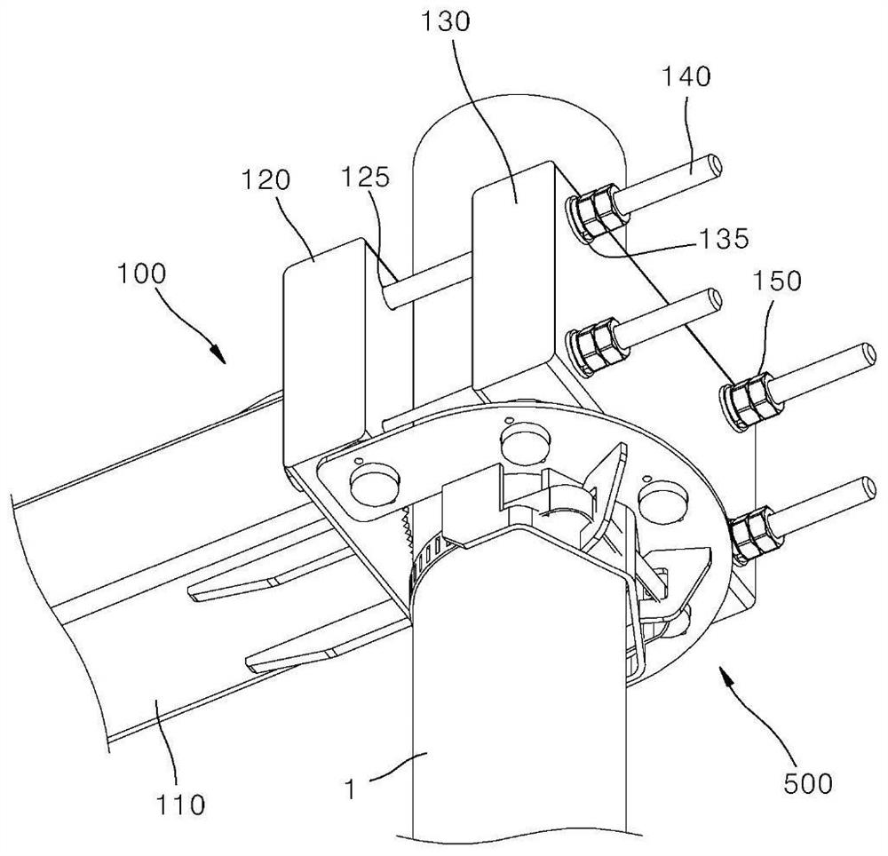
[0056] Hereinafter, an embodiment of the antenna clamp device according to the present invention will be described in detail with reference to the drawings.

[0057] When assigning reference numerals to constituent elements in each drawing, even if they appear in different drawings, the same constituent elements are assigned the same reference numerals as much as possible. Moreover, if it is judged that the detailed description of related known structures or functions may hinder the understanding of the embodiments of the present invention during the description of the present invention, the detailed description will be omitted.

[0058] In describing the structural elements of the embodiments of the present invention, the terms first, second, A, B, (a), (b), etc. may be used. Such terms are used only to distinguish a structural element from other structural elements, and the nature or order or sequence of the structural elements are not limited to the terms. And, unless othe...


PUM


Abstract

The present invention relates to a clamp device for an antenna, and more particularly, to a clamp device for an antenna, comprising: an arm unit coupled so as to extend in the horizontal direction with respect to a pole vertically provided in the vertical direction; a clamp part, one end of which is provided with an antenna device and the other end of which is coupled to the front end of the arm unit, the clamp part being capable of rotating in the left-right direction or tilting in the up-down direction so as to rotate the antenna device; and a rotation auxiliary mounting part which is coupled to the derrick corresponding to the lower part of the arm unit, and which supports the weight of the arm unit and the antenna device and rotatably supports the arm unit in the rotation direction of the arm unit when the rotation angle of the arm unit changes. The present invention provides an advantage of easily adjusting the setting and directivity of an antenna device by one designer.

Description

technical field [0001] The present invention relates to an antenna clamping device (CLAMPING APPARATUS FOR ANTENNA), and more specifically, to a clamping device for an antenna capable of supporting the total weight of an antenna device, a clamping portion for connecting the antenna device, and an arm unit , even if it is not completely separated from the pole, the directivity of the antenna can be effectively adjusted within a wide and narrow range on the pole. Background technique [0002] Wireless communication technology, for example, Multiple Input Multiple Output (MIMO, Multiple Input Multiple Output) technology is a technology that greatly increases the data transmission capacity by using multiple antennas. In the transmitter, different data are transmitted through each transmission antenna. A method of spatial multiplexing that differentiates transmitted data by appropriate signal processing in the receiver. [0003] Therefore, as the number of transmitting or receiv...

Claims


Application Information

Patent Timeline
Patent Type & Authority Applications(China)
IPC IPC(8): F16C11/04F16B2/06H01Q1/12
CPCF16C11/04F16B2/065H01Q1/1207H01Q1/1228F16B2/12H01Q3/08H01Q1/1264
Inventor 姜声满梁亨硕金仁昊朴大明李守庸
Owner KMW INC
Why Eureka
Try Eureka