Motor control device and motor control method
A technology of a control device and a control method, which is applied in the direction of motor control, AC motor control, estimation/correction of motor parameters, etc., can solve the problems of encoder and motor assembly error, encoder resolution performance, etc., and achieve low-cost effects.
- Summary
- Abstract
- Description
- Claims
- Application Information
AI Technical Summary
Problems solved by technology
Method used
Image


Examples
Embodiment 1
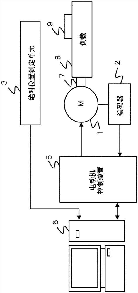
[0028] exist figure 1 A configuration example of an overall system including a servo motor control device to which the present invention is applied is shown in . The system for position correction includes a servo motor 1 as an object of position measurement, an encoder 2 for acquiring rotational position information of the servo motor 1, and a motor control device 5 such as a servo amplifier for controlling the servo motor (hereinafter simply referred to as "motor") , an absolute position measuring unit 3, an information processing device 6 such as a personal computer installed with a program for measuring and processing an error between the absolute position measuring unit 3 and the servo motor 1, a load 8 driven in accordance with the rotation of the servo motor 1, A connector 7 connecting the servo motor 1 to a load 8 , and a work object 9 attached to the load 8 . The absolute position measuring unit 3 is, for example, a laser length measuring device, and the load 8 is, f...
Embodiment 2
[0066] In Embodiment 2, it is possible to set a plurality of application ranges of error angles. Below, use Figure 9 Be explained.
[0067] Such as Figure 9 When the servo motor is assembled on a load with multiple workranges as shown, the position correction data in the case of Workrange1 is measured from the correction position N(0) to N(x), and then from the correction position N'(0 ) to N'(x) to measure the position correction data in the case of Worlrage2.
[0068] By dividing the section for performing position correction into a plurality of sections in this way, the total amount of data can be reduced, and at the same time, data can be finely collected in necessary sections, and high-precision position correction can be performed.
Embodiment 3
[0070] In the third embodiment, the position correction data when the machine origin position is changed will be described.
[0071] Figure 10A , 10B A method will be described in which the motor control device 5 obtains the position correction data in advance from the information processing device 6 and performs position correction without re-measuring the error angle even when the position of the machine origin is changed.
[0072] Assume that position correction data for performing position correction is generated in the work range Workrange from the correction start position Pstart to the correction end position Pend with the initial machine origin position Homeposition1 as a reference.
[0073]At this time, the determination of whether the position correction process is implemented or not is performed, as shown in equations (3) and (4), to determine whether the position command Pref takes the initial mechanical origin position Homeposition1 as the reference position, an...
PUM
 Abstract
Description
Claims
Application Information
 - R&D
- Intellectual Property
- Life Sciences
- Materials
- Tech Scout
- Unparalleled Data Quality
- Higher Quality Content
- 60% Fewer Hallucinations
Browse by: Latest US Patents, China's latest patents, Technical Efficacy Thesaurus, Application Domain, Technology Topic, Popular Technical Reports.
© 2025 PatSnap. All rights reserved.Legal|Privacy policy|Modern Slavery Act Transparency Statement|Sitemap|About US| Contact US: help@patsnap.com