

Compression molding equipment for biomass energy
A biomass energy and compression molding technology, which is applied in the fields of presses, solid separation, chemical instruments and methods, etc., can solve the problems of cumbersome operation and achieve the effect of convenient operation.
- Summary
- Abstract
- Description
- Claims
- Application Information
AI Technical Summary
Problems solved by technology
Method used
Image

Examples
Embodiment 1
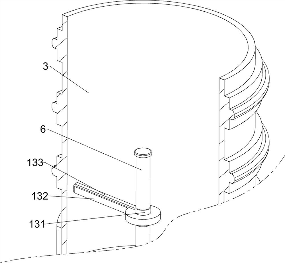
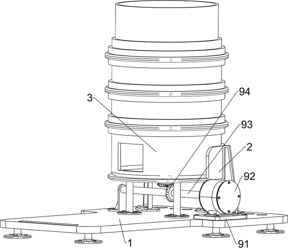
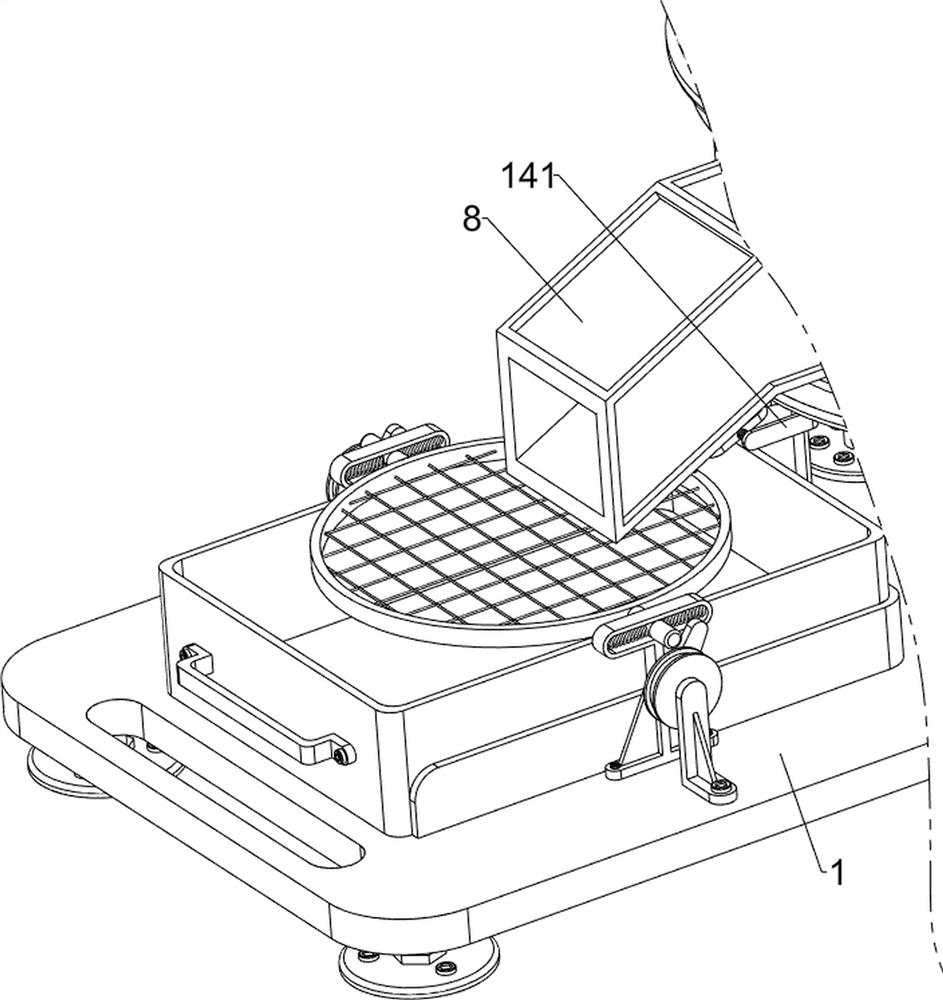
[0032] A kind of compression molding equipment for biomass energy, refer to Figure 1-2As shown, it includes a base 1, a support seat 2, a compression box 3, a compression wheel 4, a compression plate 5, a first rotating shaft 6, a first guide groove plate 7, a second guide groove plate 8, a power mechanism 9 and a screening mechanism 10 The right side of the top of the base 1 is fixed with a support seat 2 by bolts, the top of the support seat 2 is welded with a compression box 3, the compression box 3 is used for compression of biomass energy, and the lower part of the compression box 3 is welded with a first guide groove plate 7, The first guide groove plate 7 is set low on the left and high on the right. The bottom of the compression box 3 is rotated in the middle to be provided with a first rotating shaft 6. The upper side of the first rotating shaft 6 is rotated to be provided with four compression wheels 4. The compression wheels 4 are enough for biomass The energy is c...
Embodiment 2
[0037] On the basis of embodiment 1, refer to figure 1 , Figure 6 and Figure 7 As shown, an intermittent feeding mechanism 11 is also included. The intermittent feeding mechanism 11 can intermittently discharge the biomass energy that needs to be compressed into the compression box 3. The intermittent feeding mechanism 11 includes a guide cylinder 111, a mounting bracket 112, The second return spring 113, the baffle plate 114, the second contact post 115 and the second cam 116, the upper part of the compression box 3 is provided with a guide cylinder 111 by welding, and the lower part of the guide cylinder 111 is provided with a mounting bracket 112 by welding in a symmetrical manner. There is a baffle plate 114 symmetrically slidingly connected between the middle parts of the mounting brackets 112. The baffle plate 114 can intermittently not block the guide cylinder 111. A second return spring 113 is connected between the outside of the baffle plate 114 and the mounting br...
PUM
 Abstract
Description
Claims
Application Information