Millimeter wave cross scanning multi-beam array antenna based on common-cavity Rotmann lens

A technology of Rotman lens and array antenna, applied in the field of array antenna, can solve the problem that the feeding network is not easy to integrate design, and achieve the effect of reducing design complexity and occupied area

Active Publication Date: 2022-05-17
UNIV OF ELECTRONICS SCI & TECH OF CHINA
View PDF10 Cites 0 Cited by
  • Summary
  • Abstract
  • Description
  • Claims
  • Application Information

AI Technical Summary

Problems solved by technology

[0003] The document "On the mapping by a cross-correlation antenna system of partially coherent radio sources" uses cross scanning for remote brightness temperature distribution testing; the document "ZIROFFAndreas et al. Self-calibration of a 3-D-digital beamforming radar system for automotive applications with installation The three-dimensional digital beamforming radar system in "behind automotive covers" and the millimeter-wave imaging system in the literature "TELLO Juan et al. It is often decomposed into two sets of one-dimensional scanning that work independently for design, because the two sets of feed networks are not easy to achieve integrated design

Method used


Image

  • Millimeter wave cross scanning multi-beam array antenna based on common-cavity Rotmann lens
  • Millimeter wave cross scanning multi-beam array antenna based on common-cavity Rotmann lens
  • Millimeter wave cross scanning multi-beam array antenna based on common-cavity Rotmann lens

Examples


Embodiment Construction

[0023] In order to illustrate the present invention more clearly, the present invention will be further described below with reference to the accompanying drawings and embodiments.

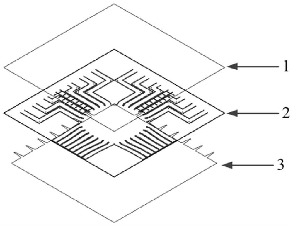
[0024] This embodiment provides a millimeter-wave cross-scanning multi-beam array antenna based on a co-cavity Rotman lens, the structure of which is as follows figure 1 and figure 2 As shown, it specifically includes: a lower-layer patch 3 , a middle-layer dielectric board 2 and an upper-layer patch 1 , which are sequentially stacked from bottom to top.

[0025] More specifically:

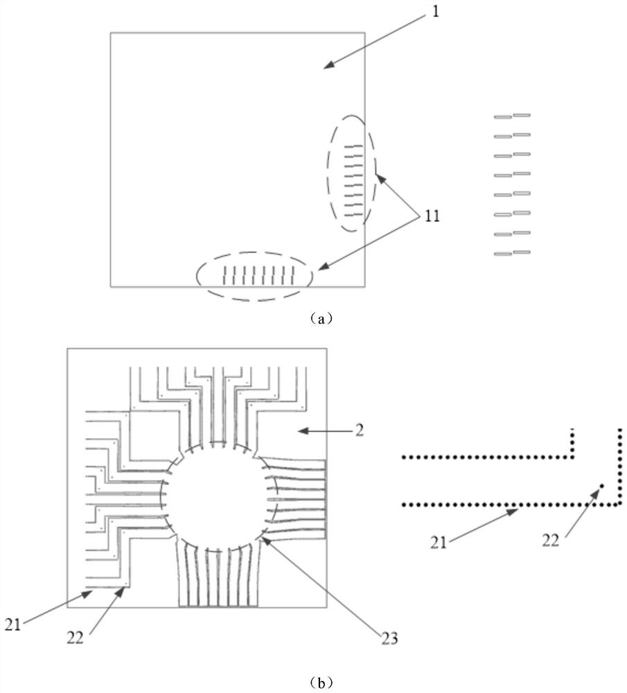
[0026] The upper layer patch such as image 3 As shown in (a), as the upper layer of the dielectric integrated waveguide and the Rotman lens, a radiation array 11 is opened on it; in this embodiment, the size of the upper layer patch is 28.9×32.1mm 2 , the radiation array 11 consists of a group of 8×2 slot antennas. The simulation model of the slot antenna is as follows Image 6 As shown, it consists of a dielect...


PUM


Abstract

The invention belongs to the technical field of array antennas, and particularly provides a millimeter wave cross scanning multi-beam array antenna based on a common-cavity Rotmann lens, a topological structure of the common-cavity Rotmann lens is adopted to feed the millimeter wave cross scanning multi-beam array antenna, the topological structure is composed of two groups of orthogonal sub-networks, each group of sub-networks is only composed of a feed source contour and inner and outer array contours (a virtual port of a traditional Rotmann lens is not added), the two groups of Rotmann lenses are orthogonally placed and form a closed common cavity (common-cavity Rotmann lenses), and the two groups of sub-networks are ensured not to be overlapped and interfered through the constraint design of the common-cavity Rotmann lenses. The input port can be switched to realize different directional angles, and the output port is connected with the radiation structure; according to the multi-beam array antenna designed based on the common-cavity Rotmann lens, the integrated design of a cross scanning feed network and a radiation structure can be realized, and the design complexity and the occupied area of the feed network are effectively reduced.

Description

technical field [0001] The invention belongs to the technical field of array antennas, and in particular relates to a millimeter-wave cross-scanning multi-beam array antenna fed by a substrate-integrated waveguide co-cavity Rotman lens, which integrates two groups of sub-feeding networks for cross scanning, Effectively reduce the design complexity and occupied area of ​​the feeding network. Background technique [0002] Millimeter-wave multi-beam array antennas have been widely used in various scenarios, such as wireless communications, radar, and imaging. Generally, multi-beam array antennas can be divided into two categories: one-dimensional scanning and two-dimensional scanning. The pattern of one-dimensional scanning multi-beam array antennas is often scanned around the azimuth or elevation angle, while the two-dimensional scanning can be around the azimuth angle at the same time. and the elevation angle for scanning; wherein, the two-dimensional scanning has a special ...

Claims


Application Information

Patent Timeline
Patent Type & Authority Applications(China)
IPC IPC(8): H01Q21/00H01Q1/38
CPCH01Q21/0031H01Q1/38
Inventor 肖烁班永灵连继伟
Owner UNIV OF ELECTRONICS SCI & TECH OF CHINA
Why Eureka
Try Eureka