Hybrid excitation multifunctional saturated iron core alternating current fault current limiter and current limiting method

A technology of fault current limiter and hybrid excitation, which is applied in AC network circuits, AC networks to reduce harmonics/ripples, emergency protection circuit devices for limiting overcurrent/overvoltage, etc., and can solve permanent magnet heating, Affect the stability of permanent magnets and current limiters, the risk of demagnetization of permanent magnets, etc., to achieve smooth regulation, reduce the risk of demagnetization, and achieve the effect of power flow regulation

Active Publication Date: 2022-05-17
WUHAN UNIV
View PDF10 Cites 0 Cited by
  • Summary
  • Abstract
  • Description
  • Claims
  • Application Information

AI Technical Summary

Problems solved by technology

An existing closed-loop iron-core hybrid excitation SCFCL topology is as follows: image 3 As shown, it further reduces the DC excitation loss of the current limiter, but the eddy current effect will be generated when the alternating magnetic flux passes through the permanent magnet, which will cause the heating problem of the permanent magnet, which will make the permanent magnet face the risk of demagnetization, and then affect the permanent magnet and Current limiter stability

Method used


Image

  • Hybrid excitation multifunctional saturated iron core alternating current fault current limiter and current limiting method
  • Hybrid excitation multifunctional saturated iron core alternating current fault current limiter and current limiting method
  • Hybrid excitation multifunctional saturated iron core alternating current fault current limiter and current limiting method

Examples


Embodiment Construction

[0030] The following will clearly and completely describe the technical solutions in the embodiments of the present invention in combination with the embodiments of the present invention. Obviously, the described embodiments are only some of the embodiments of the present invention, not all of them. Based on the embodiments of the present invention, all other embodiments obtained by persons of ordinary skill in the art without creative efforts fall within the protection scope of the present invention.

[0031] It should be noted that, in the case of no conflict, the embodiments of the present invention and the features in the embodiments can be combined with each other.

[0032] The present invention will be further described below in conjunction with specific examples, but not as a limitation of the present invention.

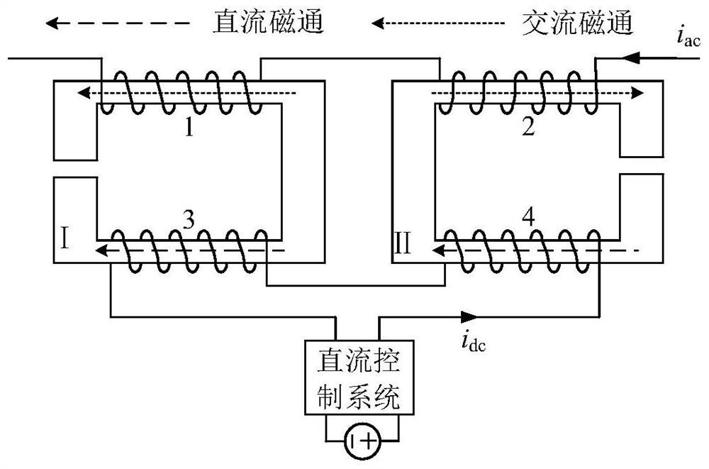
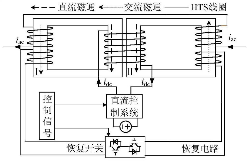
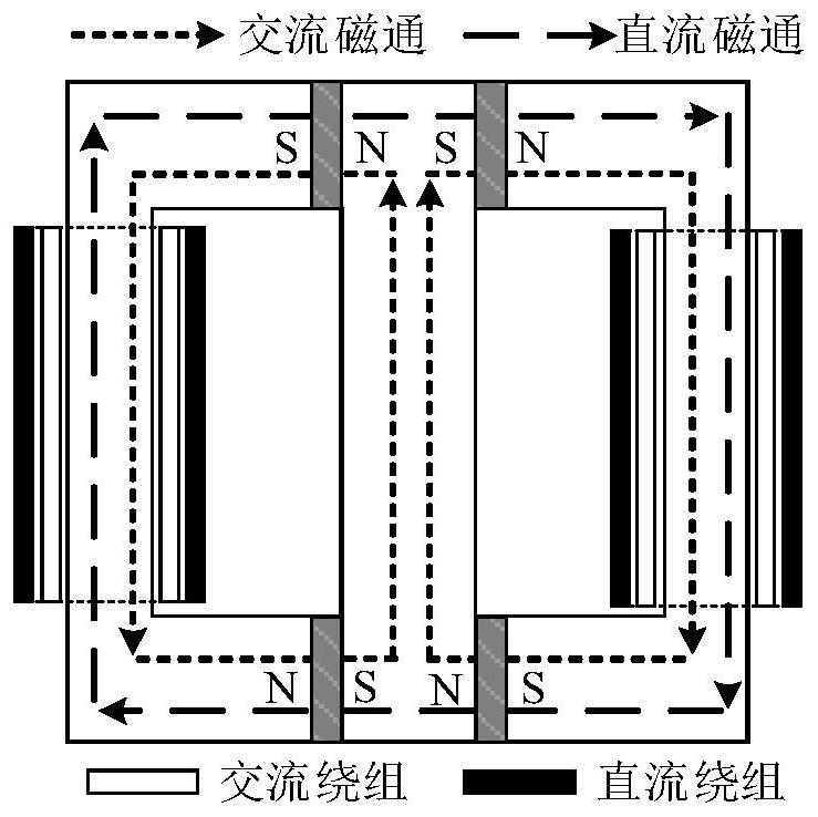
[0033]This embodiment proposes a mixed-excitation multifunctional saturated iron core fault current limiter topology. By adopting a mixed-excitation method, t...


PUM


Abstract

The invention relates to a saturated iron core type alternating current fault current limiter technology, in particular to a mixed excitation multifunctional saturated iron core alternating current fault current limiter and a current limiting method, the current limiter comprises an iron core, a first direct current winding, a second direct current winding, a first alternating current winding, a second alternating current winding and a direct current peripheral circuit; the iron core is of a five-column type structure and comprises a left outer side air gap supporting column, a right outer side air gap supporting column, a middle supporting column, a left working iron core, a right working iron core, an upper transverse yoke and a lower transverse yoke, the left working iron core is located between the left outer side air gap supporting column and the middle supporting column, and the right working iron core is located between the right outer side air gap supporting column and the middle supporting column. The upper transverse yoke and the lower transverse yoke are located above and below all the supporting columns respectively, and a permanent magnet is embedded in the middle supporting column. The current limiter can effectively adjust the power flow of a power system when the power system operates normally; when a short-circuit fault occurs in a power system, the fault current of the system is effectively limited, the eddy-current loss of the permanent magnet is reduced, and the utilization rate of the current limiter is greatly improved.

Description

technical field [0001] The invention belongs to the technical field of a saturated iron core AC fault current limiter, in particular to a hybrid excitation multifunctional saturated iron core AC fault current limiter and a current limiting method. Background technique [0002] With the improvement of the system voltage level and the continuous increase of the load scale, the short-circuit current level of the system has risen sharply, and some places even exceed the breaking capacity of the circuit breaker. The problem of excessive short-circuit current is becoming more and more serious, which brings hidden dangers to the safe and stable operation of the system, and it is imminent to take current limiting measures for the system. Fault current limiter is a very promising current limiting device. It has low steady-state impedance and high transient impedance. It can automatically switch impedance and effectively limit short-circuit current. Among them, the saturated iron cor...

Claims


Application Information

Patent Timeline
Patent Type & Authority Applications(China)
IPC IPC(8): H02H9/02H02J3/01
CPCH02H9/021H02J3/01H02J2203/20Y02E40/60
Inventor 袁佳歆叶丛韬洪永贵
Owner WUHAN UNIV
Why Eureka
Try Eureka