
Aerostatic bearing based on lotus root-shaped directional porous throttling

A gas static pressure, lotus-shaped technology, applied in the transmission field, can solve the problem that the gas static pressure bearing cannot meet the extreme precision processing requirements of optical components, and achieve the effect of reducing motion friction and low heat generation

Active Publication Date: 2022-05-20
INST OF MACHINERY MFG TECH CHINA ACAD OF ENG PHYSICS
View PDF23 Cites 0 Cited by
  • Summary
  • Abstract
  • Description
  • Claims
  • Application Information

AI Technical Summary

Problems solved by technology

[0005] The technical problem to be solved by the present invention is that the gas static pressure bearing cannot meet the extreme precision processing requirements of various optical elements, and the purpose is to provide a gas static pressure bearing based on lotus-shaped directional porous throttling, which solves the problem of the structure of the gas dynamic static pressure bearing. , bearing, stiffness and stability issues

Method used


Image

  • Aerostatic bearing based on lotus root-shaped directional porous throttling
  • Aerostatic bearing based on lotus root-shaped directional porous throttling
  • Aerostatic bearing based on lotus root-shaped directional porous throttling

Examples


Embodiment 1

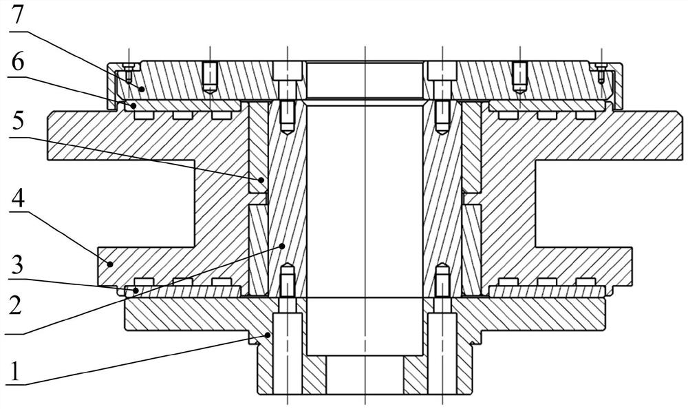
[0048] Such as figure 1 As shown, an aerostatic bearing based on a lotus-shaped directional porous throttle includes a throttle mount 4, a rotating shaft 2, a first thrust plate 7, a second thrust plate 1, and a throttle group.

[0049] The throttle mount 4 has a first plane and a second plane parallel to each other, such as figure 1 As shown, set the first plane as the upper side shown in the figure, and the second plane as the lower side shown in the figure, then the restrictor is installed on a parallel upper side and lower side, and is installed inside the restrictor mounting seat 4 An installation through hole perpendicular to the first plane and the second plane, the installation through hole is used for installation and rotation.

[0050] The rotating shaft 2 is arranged in the installation through hole of the throttle mounting seat 4, and the central axis of the rotating shaft 2 coincides with the central axis of the installation through hole; the rotating shaft 2 can...

Embodiment 2

[0059] This embodiment illustrates the structure of the restrictor group in the first embodiment.

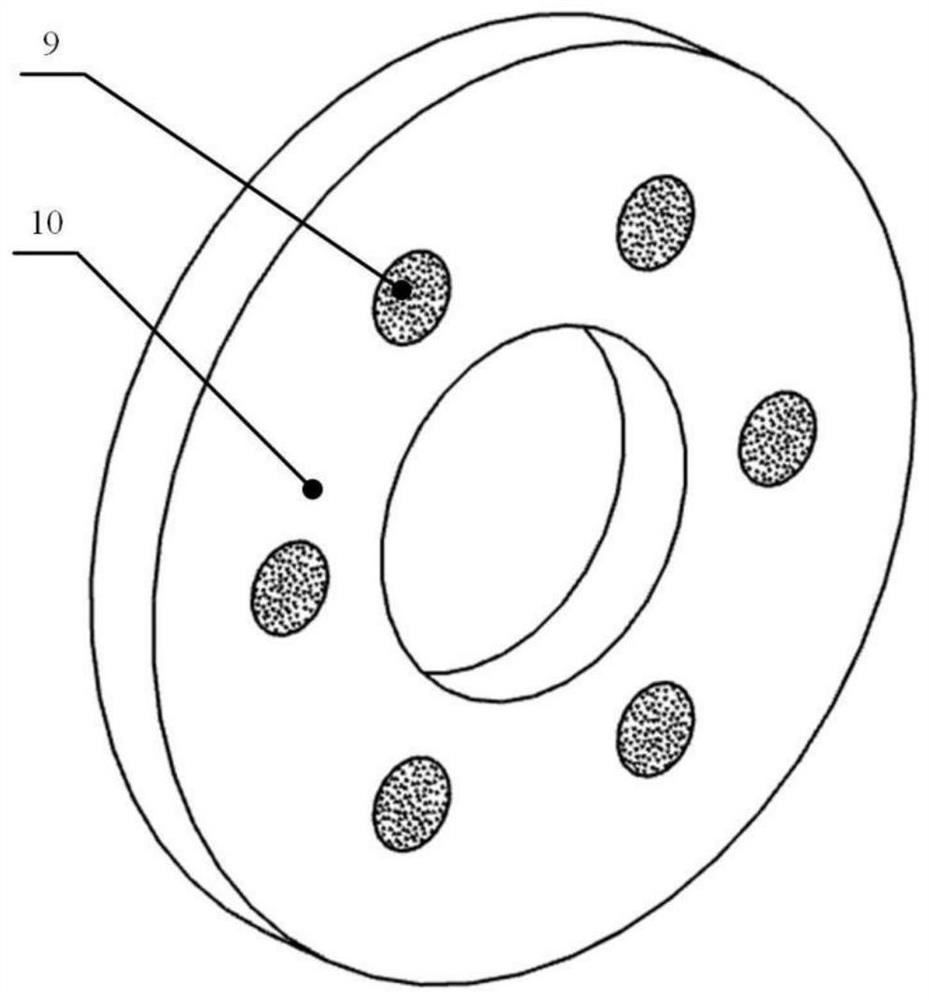
[0060] The restrictor group includes a radial restrictor 5 , a first thrust restrictor 6 and a second thrust restrictor 3 .

[0061] The radial restrictor 5 is arranged between the installation through hole and the rotating shaft 2, and the radial restrictor 5 is fixedly connected to the inner surface of the installation through hole, and its purpose is to provide a high-pressure air film between the installation through hole and the rotating shaft 2 , so that there is no contact between the outer surface of the rotating shaft 2 and the inner surface of the installation through hole.

[0062] The first thrust restrictor 6 is arranged between the first thrust plate 7 and the first plane, and the first thrust restrictor 6 is fixedly connected with the first plane. A high-pressure air film is provided between the push plates 7, so that during the rotation of the rotating shaft 2 a...

Embodiment 3

[0066] For the structures in Embodiment 1 and Embodiment 2, the high-pressure air film is used to isolate the surface of the moving pair, which can significantly reduce motion friction, and has the advantages of high precision, high speed, low heat generation, and no pollution.

[0067] According to different throttling methods, aerostatic bearings are usually divided into small hole, torus, slit and porous throttling aerostatic bearings, among which small hole throttling and porous throttling aerostatic bearings are more common .

[0068] Porous throttling aerostatic bearings have better bearing capacity, stiffness and stability, but the structure is more complex and inconvenient to process; while small hole throttling air bearings are simple in structure, mature in design, easy to process, and more stable and reliable in performance, but Based on the traditional small hole throttling method, when the gas passes through the pressure equalization chamber structure, there are o...


PUM


Abstract

The aerostatic bearing comprises a throttler mounting seat, a rotating shaft, a first thrust plate, a second thrust plate and a throttler set, mounting through holes perpendicular to a first plane and a second plane are formed in the throttler mounting seat, the rotating shaft is arranged in the mounting through holes of the throttler mounting seat, and the first thrust plate and the second thrust plate are arranged in the throttler mounting seat. The first thrust plate is fixedly connected with the first end of the rotating shaft, the second thrust plate is fixedly connected with the second end of the rotating shaft, the throttler set is located between the throttler mounting base and the first thrust plate and between the second thrust plate and the rotating shaft, and an air inlet channel communicated with the throttler set is arranged in the throttler mounting base; the throttler group is mounted between the rotating shaft and the throttler mounting seat, a high-pressure gas film is formed between the rotating shaft and the throttler mounting seat through the throttler group, and the surface of a kinematic pair is isolated by the high-pressure gas film, so that the kinematic friction can be remarkably reduced, and the high-precision high-speed low-heat-emission motor has the advantages of high precision, high speed, low heat emission, no pollution and the like.

Description

technical field [0001] The invention relates to the technical field of transmission, in particular to an aerostatic bearing based on lotus-shaped directional porous throttling. Background technique [0002] In the processing of various optical components, bearings need to be used to connect the rotating parts. At present, more connection methods are connected by balls, rollers, etc. [0003] The above-mentioned connections are mostly rigid connections. Although they have better bearing capacity, when vibration occurs between the rotating parts, the rigid connection will transmit the vibration between the two connecting parts, resulting in the stability of the rotating shaft. Lowering the problem. [0004] At the same time, the rigid connection is adopted, and there is friction between the connecting parts, which will reduce the precision of the transmission and affect the processing efficiency. Contents of the invention [0005] The technical problem to be solved by the ...

Claims


Application Information

Patent Timeline
Patent Type & Authority Applications(China)
IPC IPC(8): F16C32/06
CPCF16C32/0622F16C32/0603
Inventor 冯艳冰崔海龙张新疆龚维纬郑越青陈刚利钱林弘俞利庆
Owner INST OF MACHINERY MFG TECH CHINA ACAD OF ENG PHYSICS
Learn More