Flexible bearing test device

A technology of flexible bearings and test devices, which is applied in the direction of mechanical bearing testing, etc., can solve the problems of flexible wheel breakage, complex structure of the test device, and impossibility of testing, etc., and achieve the effects of less fatigue damage, increased contact area, and simple structure

Active Publication Date: 2022-05-20
LUOYANG BEARING RES INST CO LTD
View PDF5 Cites 0 Cited by
  • Summary
  • Abstract
  • Description
  • Claims
  • Application Information

AI Technical Summary

Problems solved by technology

[0006] The purpose of the present invention is to provide a flexible bearing test device to solve the technical problems in the prior art that the test device has a complex structure and the flexible wheel may break before the flexible bearing, which makes the test impossible

Method used


Image

  • Flexible bearing test device
  • Flexible bearing test device

Examples


Embodiment 1

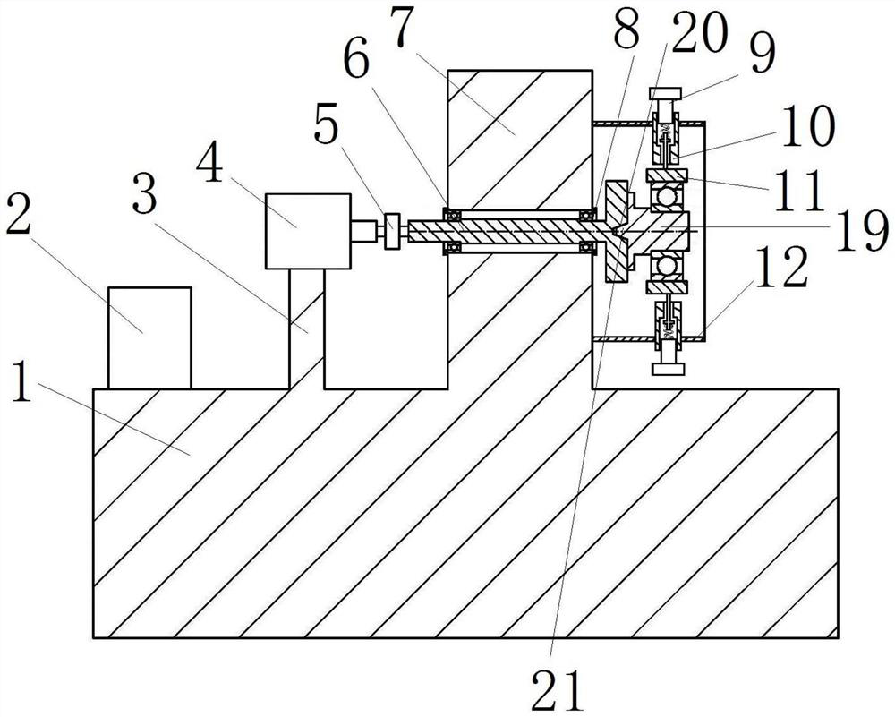
[0037] Such as figure 1 As shown, the flexible bearing test device includes a test frame 1, a control system 2 and a motor 4 are installed on the test frame 1, the motor 4 is controlled by the control system 2, the motor 4 is connected to the mandrel 6 through transmission, and the right end of the mandrel 6 is set There is an elliptical shaft 19, and the elliptical shaft 19 is used for the assembly of the flexible bearing 18 to be tested. The test frame 1 is also provided with a mounting bracket, and the mounting bracket is connected with a top pressing block 11. The top pressing block 11 is used to press the flexible bearing 18 to be tested. .

[0038] The test frame 1 is an inverted "T"-shaped structure, including a base and a support platform 7, the support platform 7 is located above the base, and the control system 2 is installed on the base of the test frame 1, and is located on the left side of the support platform 7.

[0039] The base is provided with a support frame...

Embodiment 2

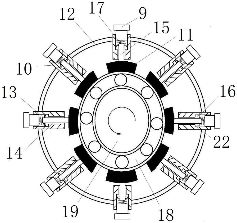
[0046] The difference between this embodiment and Embodiment 1 lies in that in Embodiment 1, the radially inner surface of the pressing block 11 is an arc-shaped pressing surface. In this embodiment, however, the radially inner surface of the pressing block 11 is a smooth plane. In other embodiments, the radially inner surface of the pressing block 11 may be a conical surface, and the conical opening faces the ellipse axis 19 .

Embodiment 3

[0048] The difference between this embodiment and Embodiment 1 is that in Embodiment 1, the adjusting bolt 9 is used as a supporting body, and is screwed into the supporting body installation part 13 of the fixing cylinder 10, and the bottom end of the adjusting bolt 9 is aligned with the fixing cylinder 10. The spring 17 forms a support. In the present embodiment, the support body can be a limit block that is slidably fitted in the support body mounting part 13 of the fixed cylinder 10, and a row of holes is opened on the fixed cylinder 10 along the axial interval of the fixed cylinder 10, and the limit block adjusts After it is in place, tighten it with a top screw, and the radial inner side of the limit block forms a support for the spring 17 in the fixed cylinder 10 .


PUM


Abstract

The invention belongs to the technical field of bearing dynamic testing, and particularly relates to a flexible bearing testing device which comprises a testing rack and further comprises a core shaft rotationally installed on the testing rack, one end of the core shaft is arranged in an overhanging mode and fixedly provided with an elliptical shaft, the elliptical shaft and the core shaft are coaxially arranged, and the elliptical shaft and the core shaft are coaxially arranged. The elliptical shaft is used for penetrating into an inner ring of the flexible bearing to be tested and is fixedly assembled with the inner ring; the test rack is further provided with an installation support arranged around the oval shaft, at least four jacking blocks are evenly distributed on the installation support in the circumferential direction of the mandrel at intervals, elastic pieces are arranged between the jacking blocks and the installation support, and the elastic pieces are used for driving the jacking blocks to abut against the outer ring of the flexible bearing in the radial direction.

Description

technical field [0001] The invention belongs to the technical field of bearing dynamic testing, and in particular relates to a flexible bearing testing device. Background technique [0002] The harmonic reducer includes a wave generator, a flexible gear (flex spline), a flexible bearing and a rigid gear (rigid spline). The wave generator is an elliptical cam structure. External gear ring, and the rigid wheel is an internal gear ring. The flexible bearings and flexible splines are all circular before they are installed in the wave generator. During assembly, the inner ring of the flexible bearing is placed on the wave generator, and the flexible wheel is placed on the outer ring of the flexible bearing. Both ends of the rear long shaft mesh with the rigid wheels to transmit power and movement. When the harmonic reducer is doing deceleration motion, the wave generator is the active part, the rigid wheel remains stationary, and the flex spline is the follower. The wave gener...

Claims


Application Information

Patent Timeline
Patent Type & Authority Applications(China)
IPC IPC(8): G01M13/04
CPCG01M13/04
Inventor 尹延经李文超王健徐润润张振强魏銮
Owner LUOYANG BEARING RES INST CO LTD
Why Eureka
Try Eureka