Oil tank waste crushing and dust removing system
A technology of dust removal system and waste, applied in the direction of plastic recycling, recycling technology, etc., can solve the problems of wasting workers' time and difficult to clean dust, and achieve the effect of saving electric energy, improving utilization rate, and avoiding too slow discharge speed.
- Summary
- Abstract
- Description
- Claims
- Application Information
AI Technical Summary
Problems solved by technology
Method used
Image
Examples
Embodiment 1
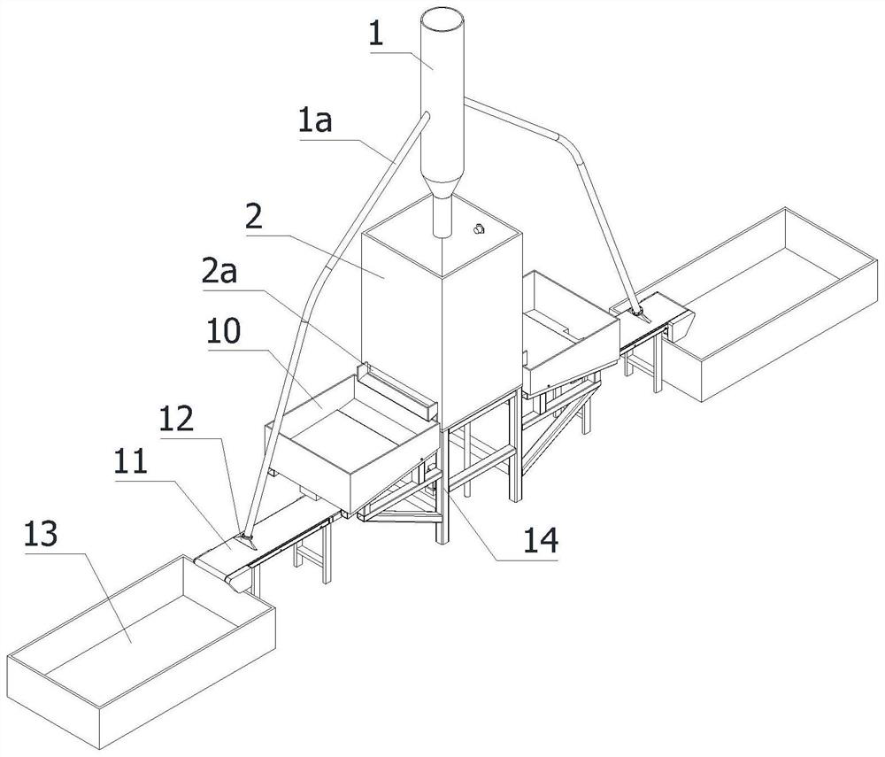
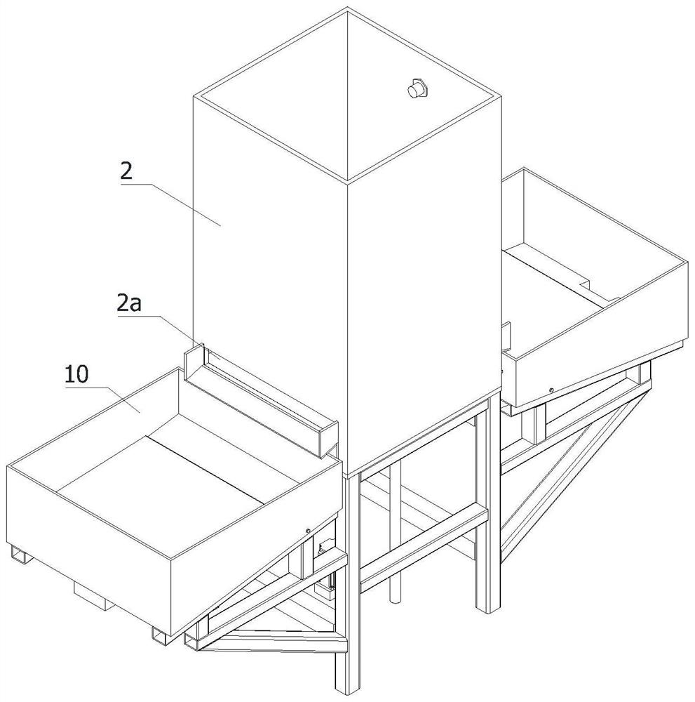
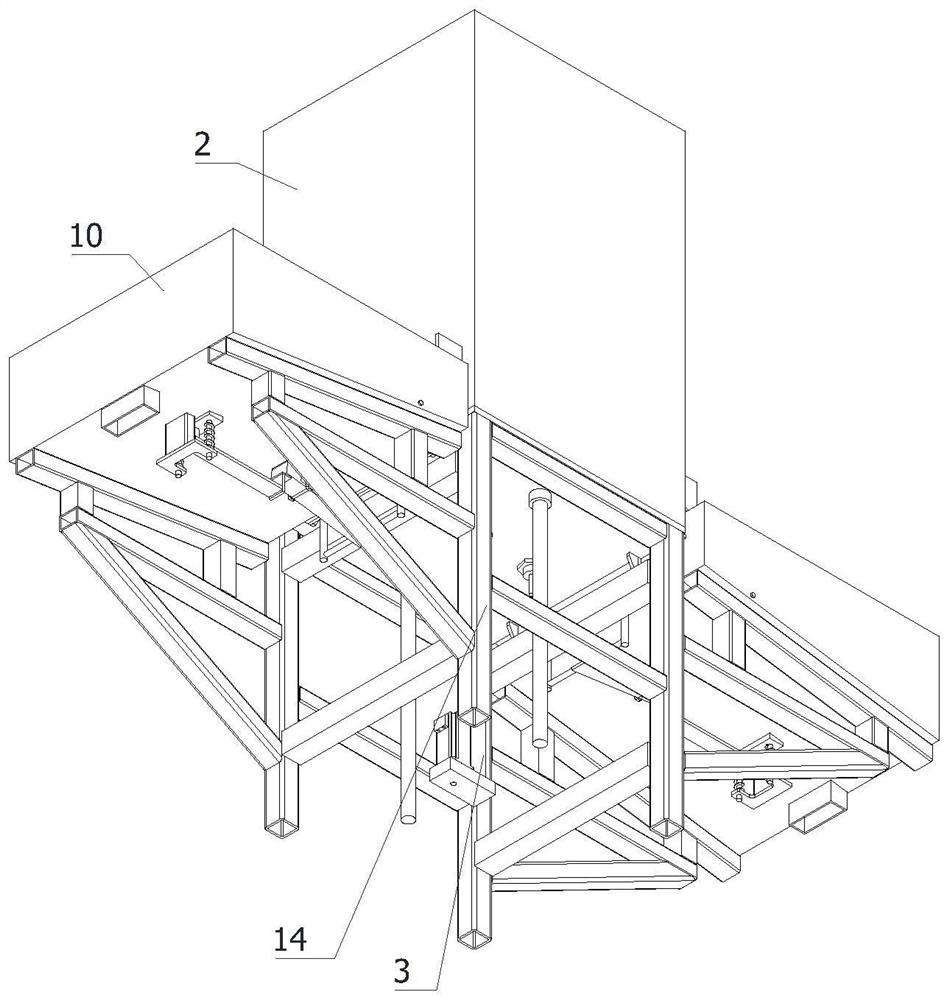
[0044] like figure 1 , figure 2 and image 3 A fuel tank waste pulverization and dust removal system shown includes a drop pipe 1, and also includes a transfer drum 2, a waste falling mechanism 3, a support frame 14 and two fine dust removal mechanisms. The transfer drum 2 is located directly below the drop pipe 1, The transfer drum 2 is fixedly installed on the support frame 14, and the waste falling mechanism 3 is fixedly installed on the transfer drum 2, which is used to control the distance between the top waste material and the discharge pipe 1. Two fine dust removal mechanisms are located on the two sides of the transfer drum 2. Of course, the two sides mentioned here are just as an example, and fine dust removal mechanisms can also be provided on the four sides of the outer edge of the transfer drum 2, and two square discharge holes 2a are provided at the bottom of both sides on the transfer drum 2. The waste in the feeding drum 2 is discharged to the fine dust remov...
Embodiment 2
[0048] This embodiment is basically the same as Embodiment 1, especially in that:
[0049] In this example, refer to Figure 4 and Figure 5 , the discharge control mechanism includes a gate mechanism 4, a reverse tilting mechanism 5, an elastic support mechanism 6, a pressure plate 7 and a transmission extension frame 8. The closing size of the discharge hole 2a, the gate mechanism 4 is fixedly installed on the bottom of the transfer drum 2, and is used to close the square discharge hole 2a, and the reverse tilt mechanism 5 is fixedly installed on the bottom of the temporary storage box 10, and the reverse tilt One end of the moving mechanism 5 is in contact with the input end of the gate mechanism 4, and the other end of the reverse tilting mechanism 5 is in contact with the transmission extension frame 8, which is used to convert the force of the transmission extension frame 8 upwardly pushing the reverse tilting mechanism 5 into Drive the power of gate mechanism 4 downwa...
Embodiment 3
[0058] This embodiment is basically the same as Embodiment 2, and the special features are:
[0059] In this example, refer to Figure 5The waste falling mechanism 3 includes a proximity sensor 3a, a first contact sensor 3b, a second contact sensor 3c, a material limiting plate 3d and an up and down push-up mechanism 3e, the material limiting plate 3d is located in the transfer drum 2, and the four sides of the material limiting plate 3d The side peripheral walls are all attached to the inner walls of the four sides of the transfer drum 2, the up and down push-up mechanism 3e is fixedly installed on the bottom of the transfer drum 2, the material limiting plate 3d is fixedly installed on the push end of the up-down push-up mechanism 3e, and the proximity sensor 3a is fixedly installed At the bottom of the transfer drum 2, it is used to limit the height of the material limiting plate 3d. The second contact sensor 3c is fixedly installed on the middle outer wall of the transfer ...
PUM
 Abstract
Description
Claims
Application Information
 - R&D
- Intellectual Property
- Life Sciences
- Materials
- Tech Scout
- Unparalleled Data Quality
- Higher Quality Content
- 60% Fewer Hallucinations
Browse by: Latest US Patents, China's latest patents, Technical Efficacy Thesaurus, Application Domain, Technology Topic, Popular Technical Reports.
© 2025 PatSnap. All rights reserved.Legal|Privacy policy|Modern Slavery Act Transparency Statement|Sitemap|About US| Contact US: help@patsnap.com


