Electric power safety fence stacking trolley

An electric safety and fence technology, applied in the field of stacking trolleys, can solve the problems of high center of gravity of the fence, potential safety hazards, and the fall of the fence, and achieve the effect of increasing the carrying capacity, improving the work efficiency, and being convenient to put in.

Pending Publication Date: 2022-05-24
STATE GRID CORP OF CHINA +2
View PDF8 Cites 2 Cited by
  • Summary
  • Abstract
  • Description
  • Claims
  • Application Information

AI Technical Summary

Problems solved by technology

The hydropower station needs to overhaul the equipment every certain period of time. During the overhaul process, it is necessary to place a power safety fence near the overhaul equipment. The safety fence can serve as a warning to prevent unrelated personnel from entering by mistake and bring safety hazards. The existing power Fences are often made of vertical glass fiber reinforced plastics. The center of gravity of the fence is high, and the fence is prone to dumping during transportation, causing safety hazards

Method used


Image

  • Electric power safety fence stacking trolley
  • Electric power safety fence stacking trolley
  • Electric power safety fence stacking trolley

Examples


Embodiment 1

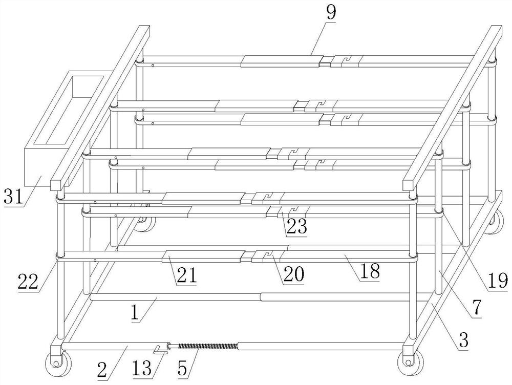
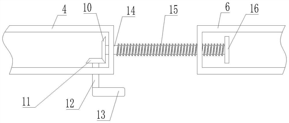
[0025] Example 1. An electric safety fence stacking trolley is composed of Figure 1-4 As shown, it includes a bottom support frame, and the bottom support frame includes a telescopic rod 1 and an adjustment rod 2 that are parallel to each other. 2 includes an adjustment section 4, the adjustment section 4 is connected to the movement section 6 through the screw rod 5, the upper end of the connecting rod 3 is evenly provided with a plurality of vertical support rods 7, and the upper end of the vertical support rod 7 is provided with a top limit corresponding to the bottom support frame The vertical support rod 7 is provided with a split limit rod group 9.

[0026] The screw rod 5 includes a smooth section 14 connected with the adjustment section 4 and a threaded section 15 connected with the moving section 6 .

[0027] The adjusting section 4 is connected to the smooth section 14 of the screw rod 5 through a bearing. The adjusting section 4 is provided with a first bevel gea...

Embodiment 2

[0035] In Embodiment 2, on the basis of Embodiment 1, a screw seat is set in the movement section 6 instead of directly setting a thread in the movement section 6, so that it is convenient to replace when damage occurs, and the replacement is convenient.

Embodiment 3

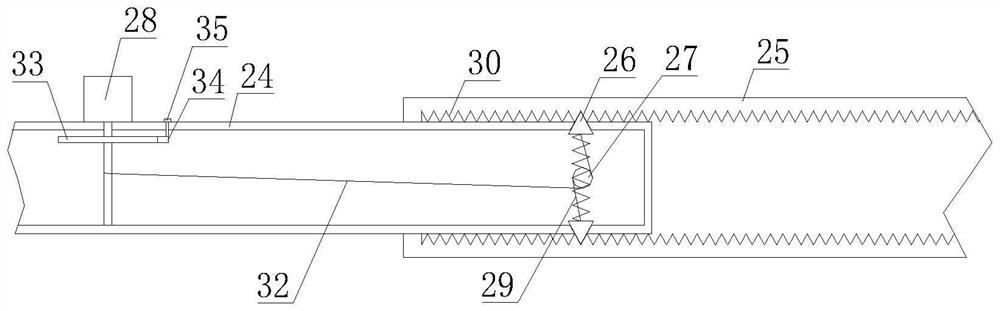
[0036] Embodiment 3, on the basis of Embodiment 1, a ratchet wheel is provided on the knob 28. When the knob 28 is rotated to shrink the lock catch 26, the pawl 34 can hold the knob 28, so that the lock catch 26 cannot be under the action of the spring. Reply directly to avoid the need for the staff to always hold the knob 28 with one hand, so that the staff can better adjust the length of the second limit rod 21. After the adjustment, by turning the lever 35, the ratchet 33 will be between the locks 26. The inner rod 24 and the outer rod 25 are fixed by rotating under the action of the spring.

[0037]The working principle of the present invention: the length of the trolley is adjusted by the number of electric safety fences to be loaded. The length of the trolley can be realized by rotating the rocker 13. When the rocker 13 rotates, it will drive the second bevel gear 11 to rotate, and the second bevel gear 11. Meshing the first bevel gear 10 makes the first bevel gear 11 al...


PUM


Abstract

The invention discloses an electric safety fence stacking trolley which comprises a bottom supporting frame, the bottom supporting frame comprises a telescopic rod (1) and an adjusting rod (2) which are parallel to each other, the two ends of the telescopic rod (1) and the two ends of the adjusting rod (2) are connected through a connecting rod (3) perpendicular to the telescopic rod (1) and the adjusting rod (2), the adjusting rod (2) comprises an adjusting section (4), and the adjusting section (4) is connected with a moving section (6) through a lead screw (5). A plurality of vertical supporting rods (7) are evenly arranged at the upper end of the connecting rod (3), a top limiting frame corresponding to the bottom supporting frame is arranged at the upper ends of the vertical supporting rods (7), and split limiting rod sets (9) are arranged on the vertical supporting rods (7). The length of the stacking trolley can be changed according to the number of carried fences, the fences can be supported and prevented from toppling over, and the safety is improved while the carrying efficiency is improved.

Description

technical field [0001] The invention relates to a stacking trolley, in particular to an electric safety fence stacking trolley. Background technique [0002] A hydropower station is a place where the potential and kinetic energy of water is converted into electrical energy. Its basic production process is: divert water from the heights of rivers or other reservoirs, use the pressure or flow rate of water to drive the turbine to rotate, convert gravitational potential energy and kinetic energy into mechanical energy, and then the turbine drives the generator to rotate to convert the mechanical energy into electrical energy. The hydropower station needs to overhaul the equipment after a certain period of time. During the overhaul process, it is necessary to place a power safety fence near the overhaul equipment. The safety fence can play a warning role to prevent unrelated personnel from entering by mistake, which will bring potential safety hazards. The fence is often made o...

Claims


Application Information

Patent Timeline
Patent Type & Authority Applications(China)
IPC IPC(8): B62B3/02
CPCB62B3/02Y02E10/20
Inventor 陈鸿峰詹云龙聂春侯彬徐鑫华方雅倩蒋梦莹
Owner STATE GRID CORP OF CHINA
Why Eureka
Try Eureka