A kind of unmanned aerial vehicle dynamic take-off and landing device and take-off and landing method
A drone and dynamic technology, applied in the field of drones, can solve the problems of affecting the efficiency of drone tasks, inconvenient adjustment of drone take-off and landing devices, and difficult take-off and landing of drones, so as to save power, Optimal Design, Isolation Effects of Carrier Perturbations
- Summary
- Abstract
- Description
- Claims
- Application Information
AI Technical Summary
Problems solved by technology
Method used
Image
Examples
Embodiment 1
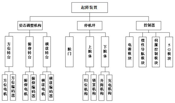
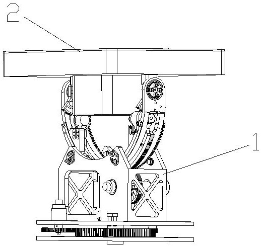
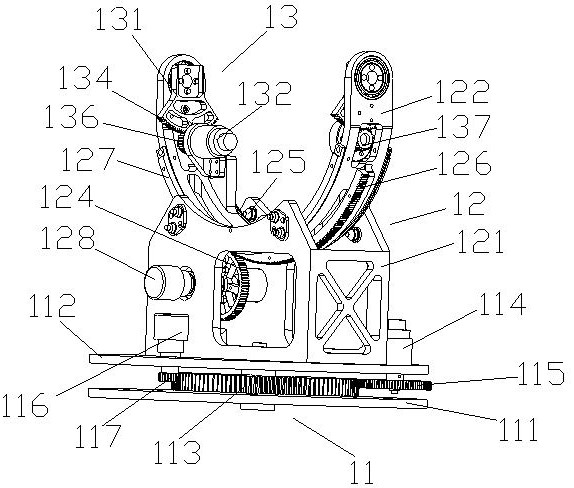
[0081] Example 1, please refer to figure 1 and figure 2 As shown in the figure, the embodiment of the present invention provides a dynamic take-off and landing device for an unmanned aerial vehicle, which is installed on the base of a carrier (mobile carrier such as a vehicle, a ship, etc.) Pad 2, the attitude adjustment mechanism 1 is set on the carrier base to dynamically adjust the posture state of the apron 2, and there is a parking space for storing the drone in the apron; the apron 2 is placed above the attitude adjustment mechanism 1 , the control unit is placed on the carrier to form the UAV take-off and landing device, the attitude adjustment mechanism 1 is designed with a U-shaped frame, and the compact space is reasonably utilized, and a reasonable space is reserved to place the lower cabin of the apron 2, so as to minimize the attitude adjustment mechanism 1 , optimal design;
[0082] During the take-off and landing of the UAV, the take-off and landing device is...
Embodiment 2
[0108] Embodiment 2, the embodiment of the present invention also provides a method for dynamic take-off and landing of an unmanned aerial vehicle, the method includes a take-off method and a landing method;
[0109] like Figure 10 As shown, the take-off method includes the following steps:
[0110] After the servo control module receives the take-off command, it integrates the speed and attitude information of the inertial navigation module for stabilization control to isolate the carrier disturbance. The expression of the three-axis frame speed compensation is as follows:
[0111]
[0112]
[0113]
[0114] in, , , are the azimuth, roll, and pitch angular velocities, respectively; , , is the component along the coordinate axis of the carrier angular velocity output by the inertial navigation module, , is the azimuth and roll frame angle values;
[0115] When the space level stability accuracy of the take-off and landing device is less than 0.5°, the ...
PUM
 Abstract
Description
Claims
Application Information
 - R&D
- Intellectual Property
- Life Sciences
- Materials
- Tech Scout
- Unparalleled Data Quality
- Higher Quality Content
- 60% Fewer Hallucinations
Browse by: Latest US Patents, China's latest patents, Technical Efficacy Thesaurus, Application Domain, Technology Topic, Popular Technical Reports.
© 2025 PatSnap. All rights reserved.Legal|Privacy policy|Modern Slavery Act Transparency Statement|Sitemap|About US| Contact US: help@patsnap.com


