Discharging device of vacuum rotary kiln

A discharge device and rotary kiln technology, applied in the direction of rotary drum furnace, furnace, furnace type, etc., can solve the problems of inability to guarantee high temperature resistance, cooling and sealing performance, so as to ensure sealing, prevent gas leakage, and prevent internal gas The effect of the leak

Active Publication Date: 2022-05-24
常州市东工自动化装备有限公司
View PDF4 Cites 0 Cited by
  • Summary
  • Abstract
  • Description
  • Claims
  • Application Information

AI Technical Summary

Problems solved by technology

After the material is conveyed out after being processed by a high-temperature drum, the traditional screw conveying method cannot guarantee high temperature resistance, cooling and sealing performance during the process of conveying the material

Method used


Image

  • Discharging device of vacuum rotary kiln
  • Discharging device of vacuum rotary kiln
  • Discharging device of vacuum rotary kiln

Examples


Embodiment Construction

[0025] The technical solutions of the present invention will be clearly and completely described below with reference to the accompanying drawings. Obviously, the described embodiments are a part of the embodiments of the present invention, but not all of the embodiments. Based on the embodiments of the present invention, all other embodiments obtained by those of ordinary skill in the art without creative efforts shall fall within the protection scope of the present invention.

[0026] In the description of the present invention, it should be noted that the terms "center", "upper", "lower", "left", "right", "vertical", "horizontal", "inner", "outer", etc. The indicated orientation or positional relationship is based on the orientation or positional relationship shown in the accompanying drawings, which is only for the convenience of describing the present invention and simplifying the description, rather than indicating or implying that the indicated device or element must hav...


PUM


Abstract

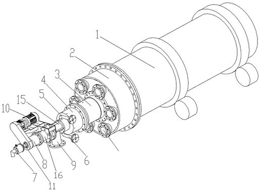
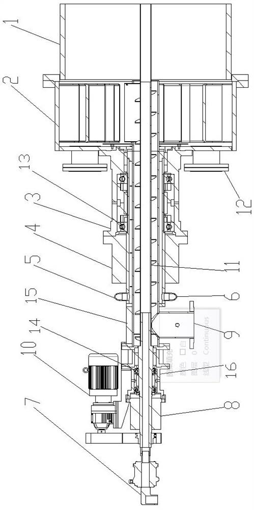
The invention relates to a discharging device of a vacuum rotary kiln, the vacuum rotary kiln comprises a high-temperature roller for reaction treatment and a receiving cylinder for sending out materials, the receiving cylinder is fixedly connected with the high-temperature roller, an inner cavity of the receiving cylinder is communicated with the high-temperature roller, and the discharging device comprises a discharging pipe, a spiral conveying shaft and a driving mechanism; the discharging pipe is externally connected to the outer side of the connecting cylinder, the spiral conveying shaft is arranged in the discharging pipe in a penetrating mode, a discharging port is formed in the discharging pipe, the driving mechanism is in transmission connection with the spiral conveying shaft and used for driving the spiral conveying shaft to act, a wall plate of the discharging pipe is a double-layer plate with an inner cavity, and the inner cavity of the double-layer plate is communicated with the discharging port. A water inlet and a water outlet are formed in the wall plate, and a water circulation structure for cooling is formed in the inner cavity. The high-temperature roller has a good cooling effect and better heat resistance, and meanwhile, the sealing performance of the high-temperature roller and the discharging section is effectively guaranteed.

Description

technical field [0001] The invention relates to the technical field of conveying equipment, in particular to a discharging device for a vacuum rotary kiln. Background technique [0002] Rotary kiln refers to rotary calcining kiln. Traditional rotary kiln belongs to building materials equipment. According to different materials, it can be divided into cement kiln, metallurgical chemical kiln and lime kiln. It is widely used in high-temperature incineration treatment, and the high-temperature incineration device of rotary kiln is widely used because of its high incineration temperature, high incineration efficiency, and low reduction rate after disposal. [0003] The rotary kiln (rotary kiln) includes a cylindrical object with a certain slope, and at the same time, the cylinder is heated at a high temperature from the outside, which can be called a high-temperature drum. The rotation of the high-temperature drum promotes the stirring of the materials in the kiln, so that the m...

Claims


Application Information

Patent Timeline
Patent Type & Authority Applications(China)
IPC IPC(8): F27B7/38F27B7/24F27B7/33
CPCF27B7/33F27B7/38F27B7/24Y02P10/25
Inventor 李冬云刘伟
Owner 常州市东工自动化装备有限公司
Why Eureka
Try Eureka