Fixing device used for blood purification nursing and capable of preventing pipeline from moving
A blood purification and fixing device technology, applied in catheters, hypodermic injection devices, dialysis systems, etc., can solve the problems of infusion tube shaking, infusion tube displacement, unfavorable operation by medical personnel, etc., and achieve the effect of avoiding damage
- Summary
- Abstract
- Description
- Claims
- Application Information
AI Technical Summary
Problems solved by technology
Method used
Image
Examples
Embodiment 1
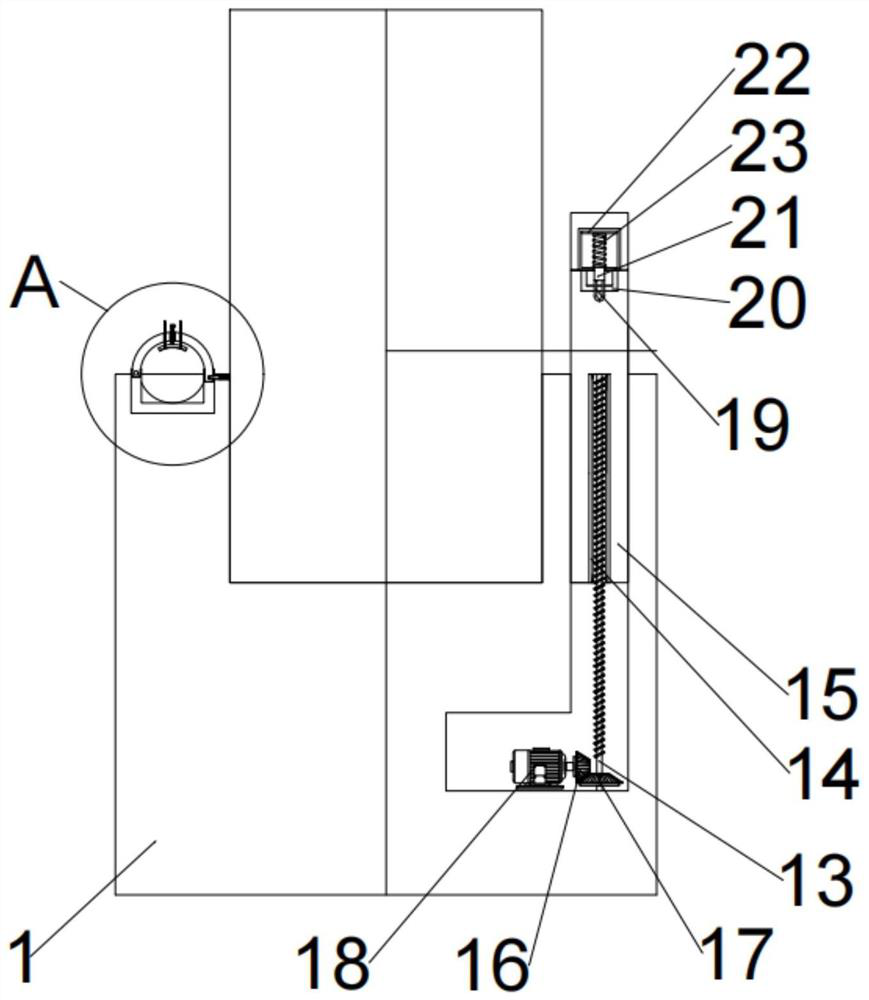
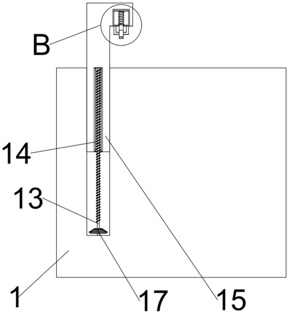
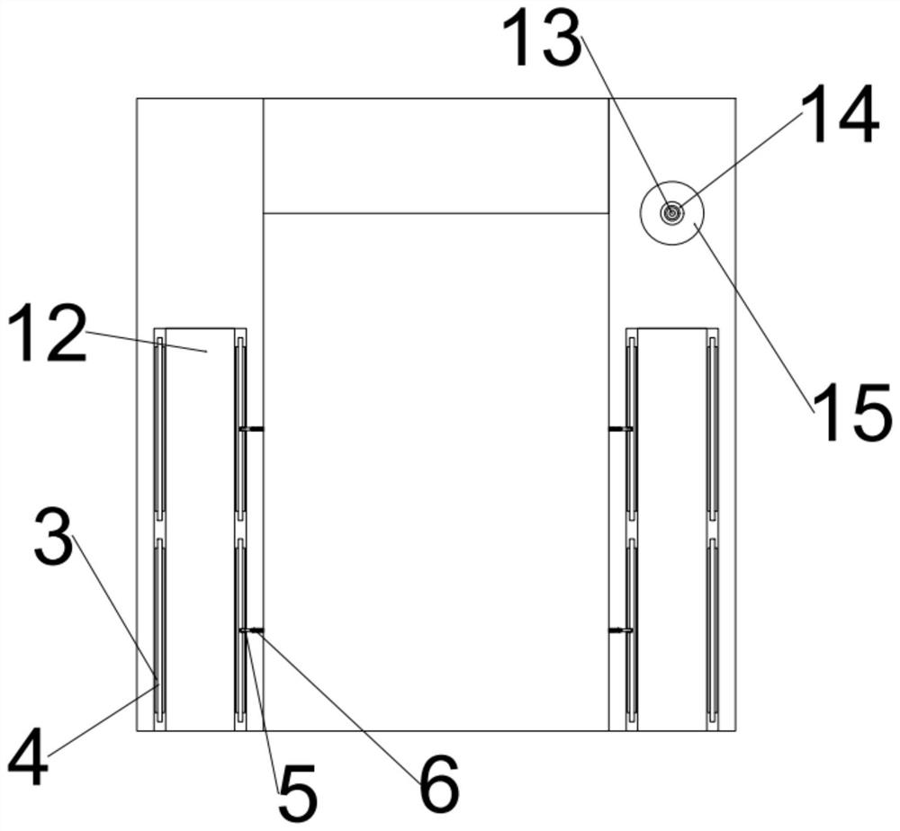
[0027] like Figure 1-3 As shown, a pair of concave arm limit blocks 2 are installed on both sides of the auxiliary seat 1, and a pipeline limit structure is installed on the auxiliary seat 1, and a pair of concave arm limit blocks 2. Arm limit structure is installed on it;
[0028] Specifically, the arm limit structure includes: two pairs of semicircular rotating cover plates 3, two pairs of turning shafts 4, two pairs of T-shaped plug-in limit rods 5, two pairs of extrusion sleeve springs 6, two pairs of rotation adjustment Handle 7, two pairs of rotation limiting threaded rods 8, two pairs of rotation limiting threaded tubes 9, two pairs of arc limiting blocks 10, two pairs of arc rubber pads 11 and a pair of arc support rubber pads 12;
[0029] Specifically, two pairs of rotation slots and two pairs of positioning slots are respectively provided on a pair of concave arm limit blocks 2, and two pairs of turning shafts 4 are respectively mounted on the inner sides of the tw...
Embodiment 2
[0032] like Figure 1-3 As shown, the pipeline limit structure includes: limit lift threaded rod 13, limit lift thread pipe 14, lift support frame 15, lift drive helical gear 16, lift drive helical gear 17 and lift drive machine 18;
[0033] Specifically, the auxiliary seat 1 is provided with a lifting convex groove, the limit lifting threaded rod 13 is inserted into the inner side of the lifting convex groove through a bearing, and the lifting driver 18 is installed on the lifting convex groove. The inner side of the convex groove, the lifting drive helical gear 16 is installed on the driving end of the lifting driver 18, the lifting drive helical gear 17 is installed on the limit lifting threaded rod 13, and the lifting drive The helical gear 17 is gear-engaged with the lifting drive helical gear 16 , and the lifting support frame 15 is installed on the limiting lifting threaded pipe 14 .
[0034]When in use, the lift driver 18 runs to drive the lift drive helical gear 16 o...
Embodiment 3
[0036] like Figure 1-3 As shown, the limited extrusion structure is installed on the auxiliary seat 1 and the lifting support frame 15;
[0037] Specifically, the limiting extrusion structure includes: several circular arc flexible limiting blocks 19, several concave pipe plates 20, several stretching limiting telescopic rods 21, several limiting plates 22 and several limiting Bit set spring 23;
[0038] Specifically, the auxiliary seat 1 and the lifting support frame 15 are provided with a plurality of convex limit grooves, and the plurality of arc flexible limit blocks 19 are respectively installed on the plurality of stretch limiters. On the telescopic rod 21, several of the limiting plates 22 are movably inserted inside the several of the convex limiting grooves respectively, and the several of the concave piping plates 20 are respectively installed on the auxiliary seat 1 and the On the lifting support frame 15, a plurality of said stretching limit expansion rods 21 ar...
PUM
 Abstract
Description
Claims
Application Information
 - R&D Engineer
- R&D Manager
- IP Professional
- Industry Leading Data Capabilities
- Powerful AI technology
- Patent DNA Extraction
Browse by: Latest US Patents, China's latest patents, Technical Efficacy Thesaurus, Application Domain, Technology Topic, Popular Technical Reports.
© 2024 PatSnap. All rights reserved.Legal|Privacy policy|Modern Slavery Act Transparency Statement|Sitemap|About US| Contact US: help@patsnap.com


