
Vertical lathe for disc

A vertical lathe, disc technology, applied in turning equipment, tool holder accessories, separation methods, etc., can solve problems such as insufficient stability, reduced processing speed, and low collection efficiency, reducing the probability of shaking and improving Processing speed, easy separation effect

Pending Publication Date: 2022-05-27
LUOYANG RUIAN NUMERICAL CONTROL MACHINE CO LTD
View PDF0 Cites 0 Cited by
  • Summary
  • Abstract
  • Description
  • Claims
  • Application Information

AI Technical Summary

Problems solved by technology

[0003] The scraps of the existing CNC vertical lathes are discharged through the chip outlet, which is easy to cause blockage, and the scraps are inconvenient to handle. The scraps contain coolant and workpiece scraps mixed, which is inconvenient to separate and collect. Inefficiency, which reduces the speed of processing
[0004] In addition, in the process of workpiece processing, it is necessary to use a fixture to fix the position of the workpiece, but the existing fixture is not stable enough when fixing the disc workpiece, and the workpiece is prone to shaking

Method used


Image

  • Vertical lathe for disc
  • Vertical lathe for disc
  • Vertical lathe for disc

Examples


Embodiment Construction

[0028] To make the object, technical solution and advantages of embodiments of the present invention more clear, the following will be combined with the accompanying drawings in the embodiments of the present invention, the technical solutions in the embodiments of the present invention are clearly and completely described, obviously, the embodiments described are part of the embodiments of the present invention, not all embodiments. Based on embodiments in the present invention, all other embodiments obtained by those of ordinary skill in the art without making creative work, are within the scope of protection of the present invention.

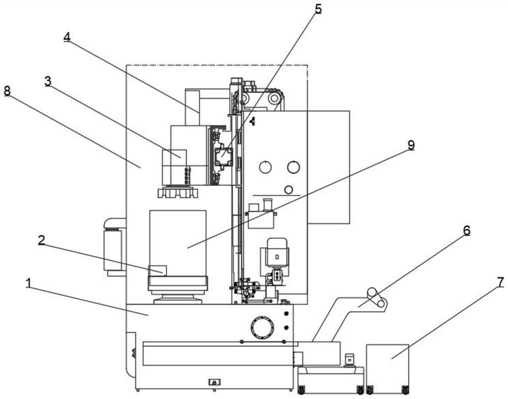
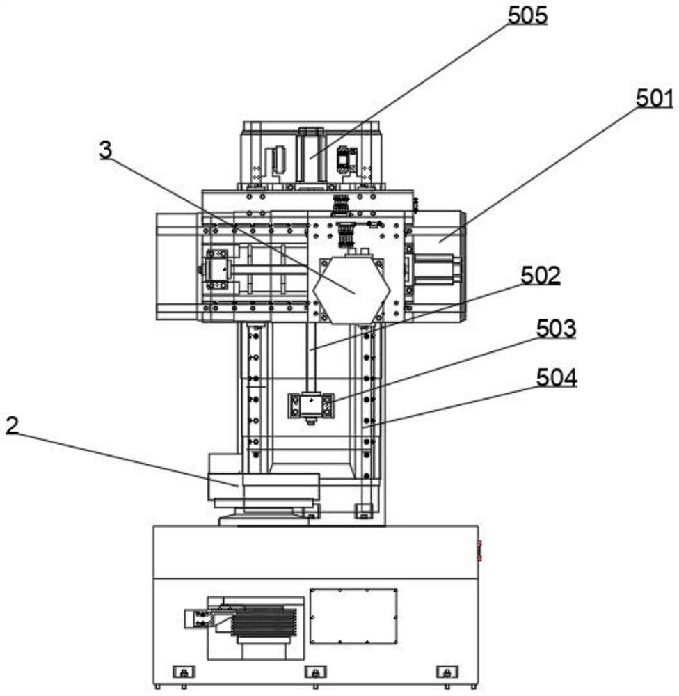
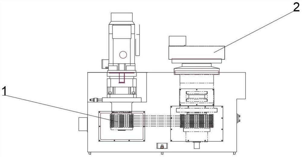
[0029] The following is a case-by-case description, please refer to Figure 1 、 Figure 4 and Figure 6 , Figure 1 Schematic diagram of the overall facing structure of the vertical lathe for the disc provided for an embodiment of the present invention, Figure 4 Schematic diagram of the chuck structure of the vertical lathe for the disc provided for ...


PUM


Abstract

The invention relates to the technical field of machining equipment, in particular to a vertical lathe for a disc, which comprises a lathe, a power mechanism and a movable turning part are arranged in the lathe, a clamping part is arranged at the output end of the power part, and the clamping part comprises a threaded rod, an auxiliary plate, a fixed block, a bottom plate, a cushion block, a connecting rod, a connecting plate and a push plate. One end of the bottom plate is fixed to the output end of the power mechanism, fixing plates are installed on the two sides of the top end of the bottom plate, a moving mechanism is arranged on one side of the top end of the bottom plate and installed on one sides of the fixing plates, fixing blocks are arranged on the opposite faces of the moving mechanism and the fixing plates, and an auxiliary plate is arranged between the moving mechanism and the fixing plates. The auxiliary plates are fixed to the two sides of the bottom plate, a chip removal channel used for discharging is formed below the clamping part, a chip removal device is arranged at the output end of the chip removal channel, separation is convenient, the collection efficiency is high, and the machining speed is increased.

Description

Technical field [0001] The present invention relates to the technical field of mechanical processing equipment, specifically to a vertical lathe for discs. Background [0002] CNC vertical lathe, with good stability and seismic performance vertical structure, easy to clamp workpieces, small footprint, suitable for processing small and medium-sized plates, cover parts high-strength cast iron base, column. [0003] The existing CNC vertical lathe has the cost of the chip through the chip discharge port, easy to cause blockage, waste chips are not convenient for processing, waste chips contain coolant and workpiece waste mixed, inconvenient to separate, the efficiency of collection is low, thereby reducing the speed of processing. [0004] In addition, in the process of workpiece processing, it is necessary to use a fixture to fix the position of the workpiece, but the existing fixture is not stable enough when fixing the disc workpiece, and the workpiece is prone to shaking. Conte...

Claims


Application Information

Patent Timeline
Patent Type & Authority Applications(China)
IPC IPC(8): B23B25/02B23B25/06B01D36/02
CPCB23B25/02B23B25/06B01D36/02Y02P70/10
Inventor 姚敬辉姚安阳
Owner LUOYANG RUIAN NUMERICAL CONTROL MACHINE CO LTD
Learn More