Check patentability & draft patents in minutes with Patsnap Eureka AI!

Numerical control machine tool

A technology of CNC machine tools and bed bodies, which is applied in the field of machine tools and can solve problems such as workpiece clamping troubles

Active Publication Date: 2022-05-27
浙江震环数控机床股份有限公司
View PDF7 Cites 2 Cited by
  • Summary
  • Abstract
  • Description
  • Claims
  • Application Information

AI Technical Summary

Problems solved by technology

[0004] The inventor believes that: when processing a long tubular workpiece, both ends of the workpiece need to be placed between the jaws of the chuck, and then the workpiece can only be released after the jaws on the chuck clamp the workpiece, so that It is troublesome to clamp the workpiece each time

Method used


Image

  • Numerical control machine tool
  • Numerical control machine tool
  • Numerical control machine tool

Examples


Embodiment Construction

[0034]The following is combined with the attached Figure 1-4 Further elaboration of this application.

[0035] Embodiments of the present application disclose a CNC machine tool.

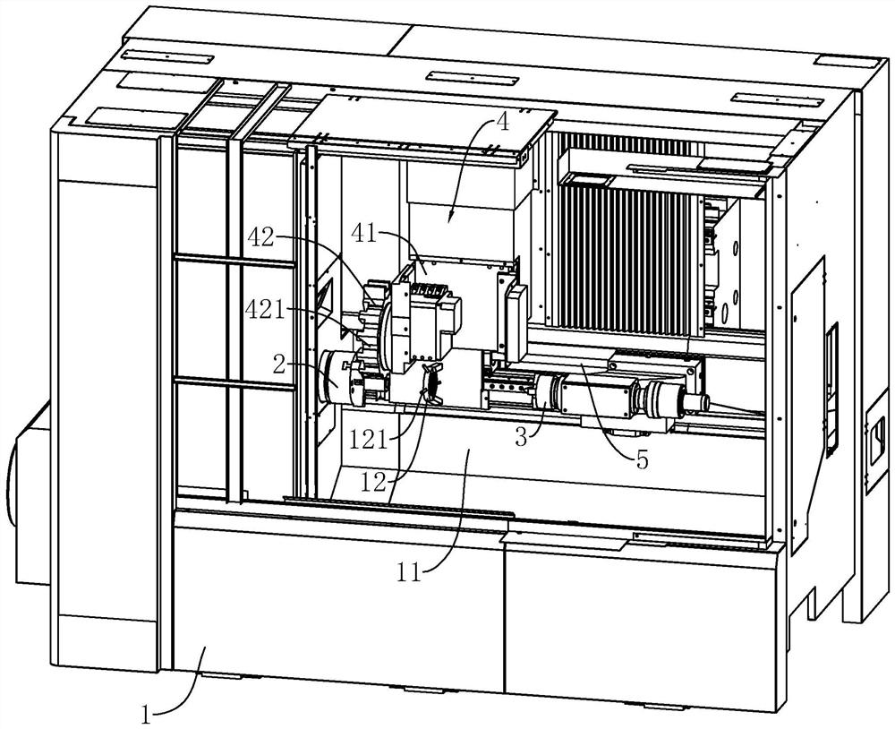
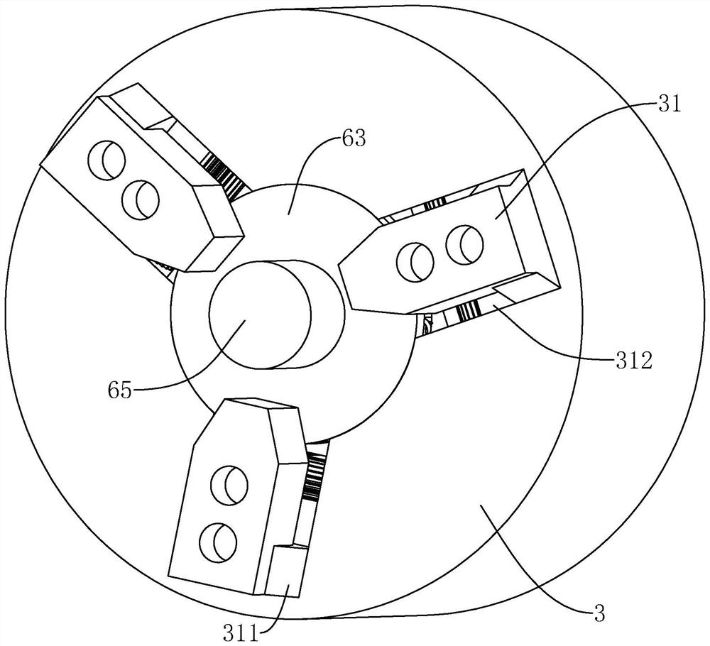
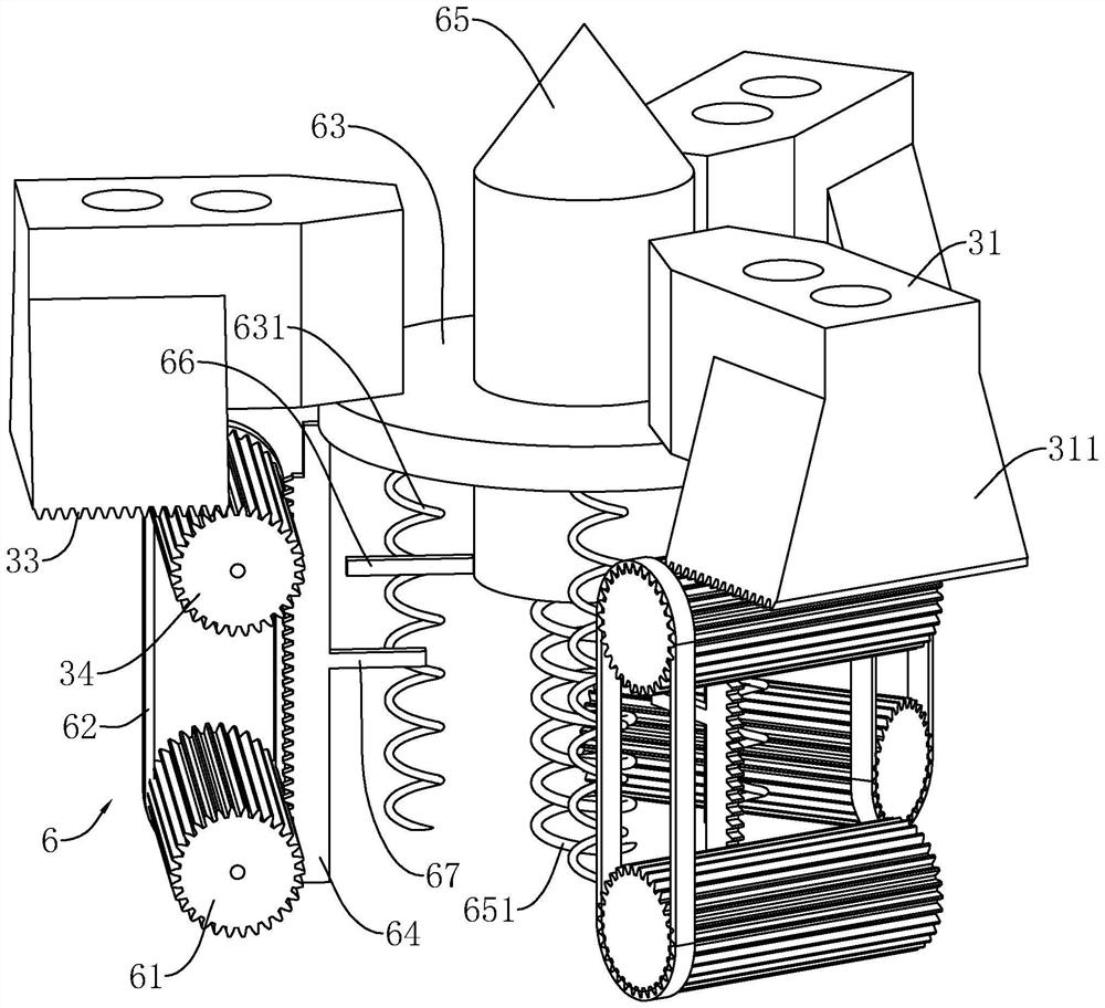
[0036] Reference Figure 1 , CNC machine tools include bed 1, main chuck 2, sub-chuck 3, cutting mechanism 4, push component 5, bed 1 is opened to accommodate the main chuck 2, sub chuck 3, cutting mechanism 4, push component 5 processing chamber 11. The main chuck 2 rotation is mounted on the bed 1, the sub-chuck 3 slips in the processing chamber 11 and the main chuck 2 corresponds, i.e., the sub-chuck 3 slides along the main chuck 2 rotation axis extension direction, while the sub-chuck 3 also rotates in the bed 1. Push assembly 5 is located at the bottom of the bed 1 to push the sub-chuck 3 to slide, the cutting mechanism 4 is located between the main chuck 2, the sub-chuck 3.

[0037] Reference Figure 1 , the cutting mechanism 4 includes a slider 41 that slides on the bed 1, a tool holder 42 that rot...


PUM


Abstract

The invention relates to a numerical control machine tool, and relates to the technical field of machine tools, the numerical control machine tool comprises a machine tool body, a main chuck arranged on the machine tool body and an auxiliary chuck slidably arranged on the machine tool body, the machine tool body is provided with a cutting mechanism for cutting a workpiece, the machine tool body is further provided with a pushing assembly for pushing the auxiliary chuck to move, and a mounting groove for containing the workpiece is formed in the main chuck; a positioning column extending into the workpiece is arranged in the auxiliary chuck and corresponds to the mounting groove. By arranging the mounting groove and the positioning column, a workpiece can be hung on the main chuck and the auxiliary chuck in advance, the workpiece can be conveniently clamped and fixed by moving the auxiliary chuck towards the main chuck after being put down, and therefore the machining device has the advantage that the long tubular workpiece can be conveniently machined.

Description

Technical field [0001] The present application relates to the field of machine tool technology, in particular to a cnc machine tool. Background [0002] At present, cnc machine tools are an automated machine tool equipped with a program control system, which can logically process programs with control codes or other symbolic instructions, and issue various control signals to control the actions of various components of the machine tool after calculation, and the processing is precise and fast. [0003] Generally, after the machine tool clamps the workpiece through the chuck, the motor drives the chuck to rotate, and then the chuck drives the workpiece to rotate, and then the tool is moved to the side of the workpiece for cutting processing. If the workpiece length is longer, the chuck is also installed at the other end of the workpiece, and the workpiece is clamped and rotated by the chucks at both ends, so as to facilitate the processing of the longer workpiece. [0004] The inv...

Claims


Application Information

Patent Timeline
IPC IPC(8): B23F23/06
CPCB23F23/06
Inventor 宋春燕金翼张纪友郑国撑吕旭锋
Owner 浙江震环数控机床股份有限公司
Features
  • R&D
  • Intellectual Property
  • Life Sciences
  • Materials
  • Tech Scout
  • Unparalleled Data Quality
  • Higher Quality Content
  • 60% Fewer Hallucinations
Learn More