Biomass particle power generation device

A technology for biomass pellets and power generation devices, which is applied in cleaning devices, transportation and packaging, conveyor objects, etc., can solve the problems of cumbersome activated carbon replacement process, time-consuming and labor-intensive excrement, and achieve the goal of reducing excrement residue and improving recovery rate. Effect

Inactive Publication Date: 2022-05-27
徐州富威新能源科技有限公司
View PDF0 Cites 0 Cited by
  • Summary
  • Abstract
  • Description
  • Claims
  • Application Information

AI Technical Summary

Problems solved by technology

[0004] In order to solve the above technical problems, a biomass particle power generation device is provided. This technical solution solves the problems of time-consuming and labor-intensive manual collection of livestock excrement and cumbersome replacement process of activated carbon used in the purification of exhaust gas proposed in the above-mentioned background technology.

Method used


Image

  • Biomass particle power generation device
  • Biomass particle power generation device
  • Biomass particle power generation device

Examples


Embodiment 1

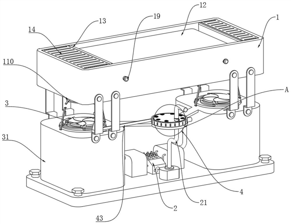
[0031] Please refer to figure 1 and Figure 5 As shown, the material storage mechanism 3 includes a collection bucket 31, a sealing turntable 32, a connecting rod 33, a sealing plate 34, a push block 35, a ball head abutting rod 36, and a triggering oblique strip 37. The bottoms of the front and rear sides of the installation bin 1 are both A collection bucket 31 is symmetrically and fixedly installed. The collection bucket 31 is an open body structure, and a sealing turntable 32 is rotatably connected to the open upper surface of the collection bucket 31. The front side of the sealing turntable 32 is located on the upper side of the collection bucket 31. The surface is provided with a push block 35, the bottom of the push block 35 is slidingly connected to the upper surface of the collecting bucket 31 through a spring, one side surface of the push block 35 is inclined, and the lower end of the push block 35 is at the inclined surface of the push block 35. On the same vertica...

Embodiment 2

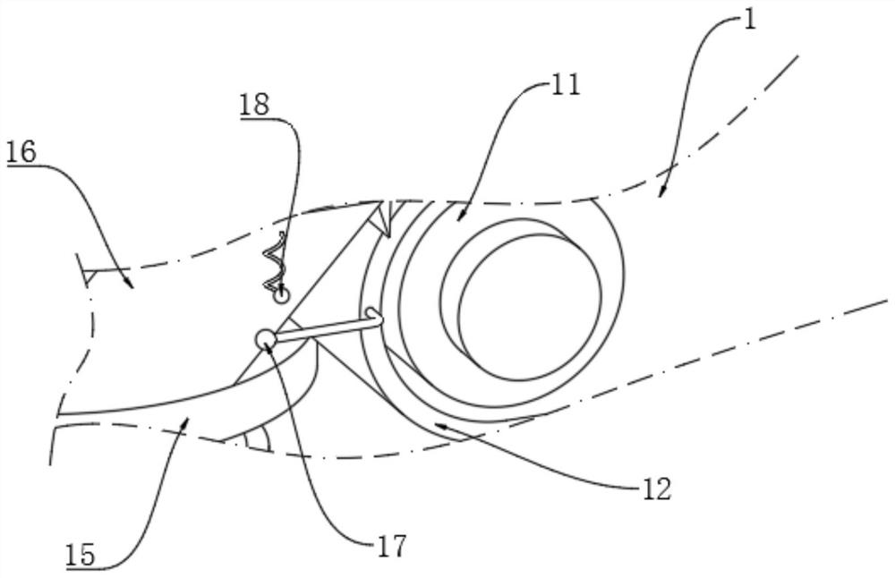
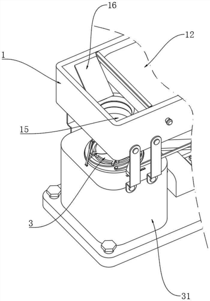
[0034] Please refer to figure 1 and figure 2 As shown, the installation bin 1 includes a rotating shaft 11, a conveyor belt 12, an attached scraper 13, a baffle plate 14, a blanking port 15, a material guide inclined plate 16, a ball-end curved shaft 17, a spring ball 18, an adjustment bolt 19, and a material storage The cavity 110, the turning ear 111, the winding shaft 112, and the suspending rope 113. The installation bin 1 is a cavity structure. The front and rear sides of the installation bin 1 are symmetrically provided with a rotating shaft 11. Bolts 19, the outer ends of the adjusting bolts 19 are placed outside the installation bin 1, the outside of the rotating shaft 11 is installed with a conveyor belt 12, both sides of the conveyor belt 12 are provided with attached scrapers 13, and the bottom surface of the attached scraper 13 is inclined There is a gap between the inner surface of the attached scraper 13 and the conveyor belt 12. The attached scraper 13 is conn...

Embodiment 3

[0038] Please refer to Figure 1 to Figure 6 As shown, a biomass particle power generation device includes an installation bin 1, a generator set 2, a material storage mechanism 3, and an adsorption mechanism 4. A generator set 2 is arranged below the installation bin 1, and the installation bin 1 includes a rotating shaft 11, Conveyor belt 12, attached scraper 13, baffle plate 14, material blanking port 15, material guide inclined plate 16, ball-end curved shaft 17, spring ball 18, adjusting bolt 19, material storage cavity 110, turning ear 111, winding shaft 112 , hanging rope 113, the installation bin 1 is a cavity structure, the front and rear sides of the installation bin 1 are symmetrically provided with a rotating shaft 11, and the center position of the front and rear sides of the rotating shaft 11 is inserted with an adjusting bolt 19, and the outer end of the adjusting bolt 19 is arranged A conveyor belt 12 is installed on the outside of the installation bin 1 and th...


PUM


Abstract

The invention discloses a biomass particle power generation device which comprises a recycling mechanism, a power generator unit, a material storage mechanism and an adsorption mechanism, the power generator unit is arranged below the recycling mechanism and comprises a main exhaust pipe, and the main exhaust pipe is arranged on the front side of the power generator unit; when excrement generated by daily activities of livestock on the conveying belt falls down and is accumulated on the surface of the conveying belt for a certain amount, the excrement can be recycled under the cooperation effect of a timing device and a driving motor, and then the excrement can be recycled. By regularly starting the external driving motor and promoting the conveying belt to convey towards the two sides, excrement on the surface of the conveying belt is gradually and automatically conveyed to the front side and the rear side of the mounting bin along with conveying of the conveying belt, so that automatic collection of the excrement is realized, and subsequent treatment links are facilitated.

Description

technical field [0001] The present invention relates to the field of power generation, in particular to a power generation device of biomass particles. Background technique [0002] Biomass particle power generation is a new type of energy utilization method, which drives the power generation device to do work by burning solid waste and other wastes to achieve the effect of power generation. At present, biomass power generation methods include: using plant straw to generate power or can also use The excrement of livestock such as cattle and sheep is produced by anaerobic treatment, and then the biogas is burned to drive the power generation device to generate electricity. [0003] At present, the power generation device using livestock raising needs to manually collect and recycle the excrement of the livestock during the use process, which is difficult to achieve the effect of automatic collection and power generation. It will cause air pollution. At present, activated car...

Claims


Application Information

Patent Timeline
Patent Type & Authority Applications(China)
IPC IPC(8): B65G45/12B65G15/00B65G23/22B65G27/10B65G47/24B65G47/38B65G65/32B01D53/04
CPCB65G45/12B65G47/24B65G15/00B65G23/22B65G27/10B65G47/38B65G65/32B01D53/04B65G2201/042B01D2253/102Y02T10/30
Inventor 刘理户
Owner 徐州富威新能源科技有限公司
Why Eureka
Try Eureka