Long-wall mining separation layer grouting drill hole arrangement method

A technology of grouting drilling and layout method, which is applied in mining equipment, earthwork drilling, safety devices, etc., and can solve problems such as grouting filling failure and easy hole plugging, so as to reduce difficulty, increase reliability and timeliness Effect

Pending Publication Date: 2022-05-27
ANHUI UNIV OF SCI & TECH
View PDF0 Cites 0 Cited by
  • Summary
  • Abstract
  • Description
  • Claims
  • Application Information

AI Technical Summary

Problems solved by technology

[0007] The present invention provides a longwall mining separated layer grouting drilling arrangement method. Compared with the traditional method, this method solves the problem that a single borehole is easy to be blocked in the traditional grouting filling process, resulting in the failure of grouting filling, increasing The reliability of the grouting filling system is improved, and the grouting is distributed through three grouting holes at the same time, which can make the slurry flow range larger, ensure that the designed grouting filling volume is achieved, and the grouting filling effect is ensured.

Method used


Image

  • Long-wall mining separation layer grouting drill hole arrangement method
  • Long-wall mining separation layer grouting drill hole arrangement method

Examples


Embodiment Construction

[0026] The invention provides a method for arranging grouting drilling holes for long-wall mining separation layers, which solves the problem that a single drilling hole is easy to block holes in the traditional grouting and filling process, which leads to the failure of grouting and filling, and increases the reliability of the grouting and filling system. At the same time, dispersed grouting through three grouting drilling holes can make the slurry flow range larger, ensure that the designed grouting filling amount is achieved, and the grouting filling effect can be ensured. Embodiments of the present invention are further described below in conjunction with the accompanying drawings:

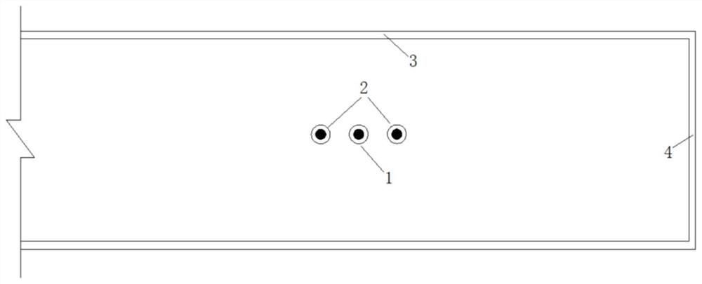
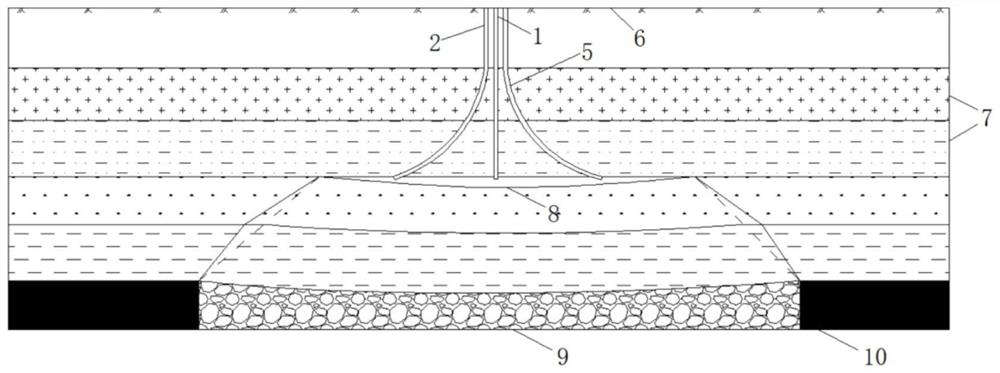
[0027] combine figure 1 , figure 2 As shown in the figure, a method for arranging drilling holes for separation layer grouting in long-wall mining, comprising:

[0028] Drill the main grouting hole 1 to the separation layer 8 from the ground 6 in the middle of the layer separation area, an...


PUM


Abstract

The invention discloses a longwall mining separation layer grouting drill hole arrangement method. The longwall mining separation layer grouting drill hole arrangement method comprises the steps that the strike length of a separation layer is determined, the diffusion radius R of slurry in a separation layer area is determined, and grouting is conducted in a target separation layer. Firstly, a vertically-downward main grouting drill hole is formed in the middle of a separation layer area to a separation layer space, then auxiliary vertical drill holes are formed in the two sides of the main grouting drill hole at the same distance to a key layer on the upper portion of the separation layer area, and then auxiliary bent drill holes are continuously drilled in the key layer to the separation layer space through directional drilling; the distance between the outlet end of the auxiliary bending drill hole and the outlet end of the main grouting drill hole is the diffusion radius of slurry. According to the method, the problem that in the traditional grouting and filling process, grouting and filling fail due to the fact that a single drill hole is prone to being blocked is solved, the reliability of a grouting and filling system is improved, meanwhile, grouting is dispersed through the three grouting drill holes, the slurry flowing range can be larger, it is guaranteed that the designed grouting and filling amount is achieved, and the grouting and filling effect is guaranteed.

Description

technical field [0001] The invention belongs to the field of grouting and filling, and in particular relates to a method for grouting drilling holes for long-wall mining separation layers. Background technique [0002] The premise of the application of the separation layer grouting technology is that the separation layer can be formed inside the overburden above the goaf after the coal seam is mined. The principle is to fill the separation layer formed by the downward movement of the overlying rock through the ground drilling to support Overburden, thereby slowing the spread of overburden movement to the surface. [0003] The traditional separation-bed grouting filling drilling arrangement only arranges one drilling hole within the coverage of the slurry diffusion radius. When using this single drilling arrangement for grouting filling, the safety factor is low due to the lack of spare drilling holes. In the process of hole grouting, when the grouting is temporarily discont...

Claims


Application Information

Patent Timeline
Patent Type & Authority Applications(China)
IPC IPC(8): E21F15/00
CPCE21F15/00
Inventor 文志强杨科于祥何祥
Owner ANHUI UNIV OF SCI & TECH
Why Eureka
Try Eureka