Lens transmittance detection device and detection method thereof

A detection device and detection method technology, applied in the direction of measuring device, optical instrument testing, testing optical performance, etc., can solve the problems of high post-work repair rate and product quality decline, etc.

Pending Publication Date: 2022-05-27
GOERTEK INC
View PDF0 Cites 0 Cited by
  • Summary
  • Abstract
  • Description
  • Claims
  • Application Information

AI Technical Summary

Problems solved by technology

[0003] The main purpose of the present invention is to propose a lens transmittance detection device and its detection method, aiming to solve the failure to identify defective products du

Method used


Image

  • Lens transmittance detection device and detection method thereof
  • Lens transmittance detection device and detection method thereof
  • Lens transmittance detection device and detection method thereof

Examples


Embodiment Construction

[0047] The technical solutions in the embodiments of the present invention will be clearly and completely described below with reference to the accompanying drawings in the embodiments of the present invention. Obviously, the described embodiments are only a part of the embodiments of the present invention, not all of the embodiments. Based on the embodiments of the present invention, all other embodiments obtained by those of ordinary skill in the art without creative efforts shall fall within the protection scope of the present invention.

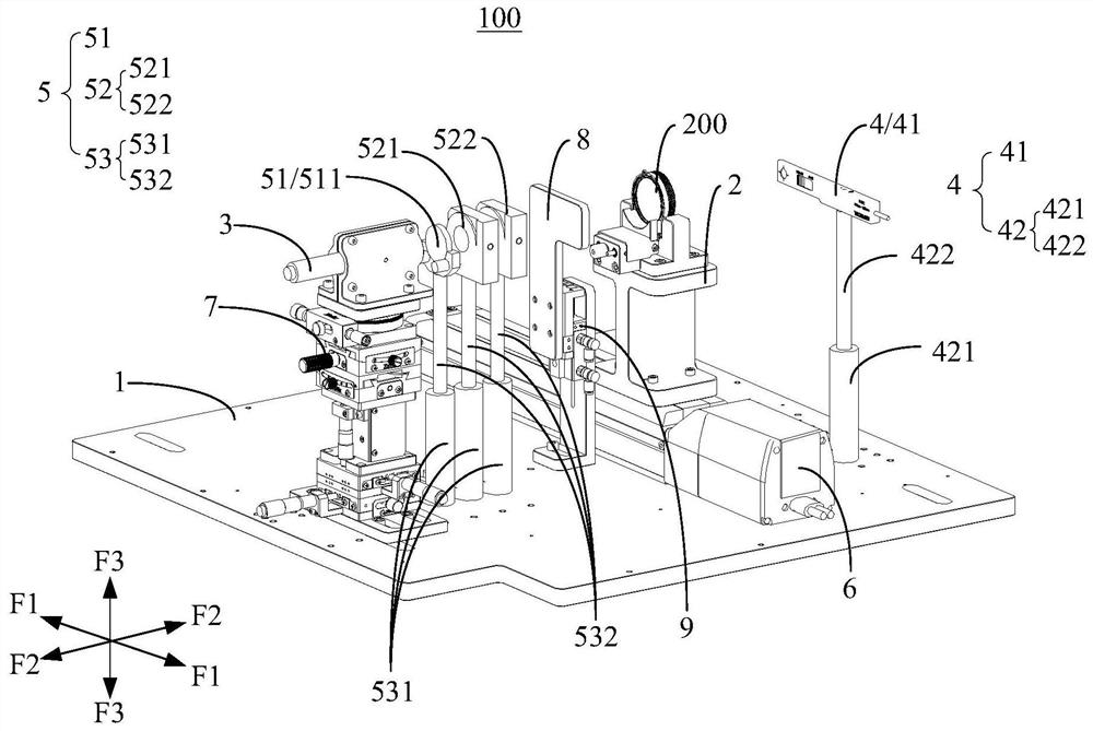
[0048] It should be noted that if there are directional indications (such as up, down, left, right, front, back, etc.) involved in the embodiments of the present invention, the directional indications are only used to explain a certain posture (as shown in the accompanying drawings). If the specific posture changes, the directional indication also changes accordingly.

[0049]In addition, if there are descriptions involving "first", "seco...


PUM


Abstract

The invention discloses a lens transmittance detection device and a detection method thereof. The lens transmittance detection device comprises a base, a bracket, a light source and a detection assembly, the base has a detection area; a lens is arranged on the bracket, the bracket is movably arranged on the base, and a first position and a second position are arranged on the movement stroke; the light source is arranged in the detection area and located on one side of the support, when the support is located at the first position, the light emitting end of the light source is opposite to the light incident side of the lens, and the light propagation path of the light source passes through the central axis of the lens; the detection assembly comprises an optical power meter, the optical power meter is arranged in the detection area and located on the other side of the support, and when the support is located at the first position, the light receiving end of the optical power meter is opposite to the light emitting end of the light source; namely, the transmissivity of the lens is detected through the lens transmissivity detection device, defective products are effectively recognized and intercepted, the qualified rate of the lens is improved, the repair rate of a rear station is reduced, and the product delivery quality is improved.

Description

technical field [0001] The invention relates to the technical field of lens detection, in particular to a lens transmittance detection device and a detection method thereof. Background technique [0002] Lenses are widely used in the optical field. Taking VR lenses as an example, VR lenses can be divided into Birdbath structure and pancake structure from their optical path design. Birdbath is also known as reflective light path, and Pancake is also known as folded light path. The basic working principle of Pancake (folded light path) is to reflect the light by using the polarization state of the light, change the polarization state and then exit; the material, coating and polarizer angle of the lens Both will affect the transmittance of light. In order to ensure that the processing and assembly of the product meet the design requirements, it is necessary to conduct a transmittance test on the lens. SUMMARY OF THE INVENTION [0003] The main purpose of the present inventio...

Claims


Application Information

Patent Timeline
IPC IPC(8): G01M11/02
CPCG01M11/02G01M11/0207G01M11/0214
Inventor 钟延天马江耿红光贾瑞龙肖欢
Owner GOERTEK INC
Why Eureka
Try Eureka