Magnetic focusing flight tube and magnetic focusing time-of-flight spectrometer

A flight tube and magnetic focusing technology, applied in the field of flight tubes, can solve the problems of low collection efficiency of electrons and ions, and achieve the effects of overcoming the decline in time resolution, fast response, and improving collection efficiency

Active Publication Date: 2022-03-25
XI'AN INST OF OPTICS & FINE MECHANICS - CHINESE ACAD OF SCI
View PDF0 Cites 0 Cited by
  • Summary
  • Abstract
  • Description
  • Claims
  • Application Information

AI Technical Summary

Problems solved by technology

[0010] In order to solve the problem of low collection efficiency of electrons and ions in existing time-of-flight spectrometers, the present invention provides a magnetic focus type flight tube and a magnetic focus time-of-flight spectrometer using the flight tube

Method used


Image

  • Magnetic focusing flight tube and magnetic focusing time-of-flight spectrometer
  • Magnetic focusing flight tube and magnetic focusing time-of-flight spectrometer
  • Magnetic focusing flight tube and magnetic focusing time-of-flight spectrometer

Examples


Embodiment 1

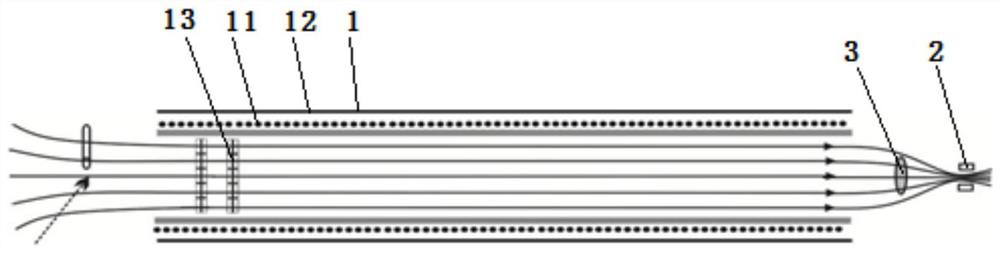
[0049] Such as figure 1 As shown, the magnetic focusing flight tube provided in this embodiment includes a flight tube main body 1, an exit strong magnet 2 and a particle detector 3;

[0050] The flight tube main body 1, the exit strong magnet 2, and the particle detector 3 are all located in the vacuum chamber;

[0051] The rear end of the exit of the flight tube main body 1 is provided with a particle detector 3 and an exit strong magnet 2 in sequence; the exit strong magnet 2 is used to concentrate the particles to be measured and be received by the particle detector;

[0052] The S pole of the exit strong magnet 2 faces the exit of the main body of the flight tube, and the particles to be measured are electrons;

[0053] Alternatively, the N pole of the exit strong magnet 2 faces the exit of the main body of the flight tube, and the particles to be measured are ions.

[0054] In the present embodiment, the flight tube main body 1 includes a solenoid 11 and a magnetically...

Embodiment 2

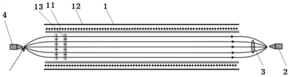
[0061] On the basis of Embodiment 1, the magnetic focus type flight tube provided in this embodiment adds an entrance strong magnet 4, and its specific structure is as follows: figure 2 Shown:

[0062] It includes an entrance strong magnet 4, a flight tube main body 1, an exit strong magnet 2, and a particle detector 3, all of which are located in the vacuum chamber;

[0063] The front end of the entrance of the flight tube main body 1 is provided with an entrance strong magnet 4, which is used to deflect the particles to be measured into the flight tube main body 1, and the rear end of the exit of the flight tube main body 1 is sequentially provided with a particle detector 3 and an exit strong magnet 2; the exit strong magnet 2 is used to make the particles to be measured converged and then received by the detector.

[0064] In this embodiment, the entrance strong magnet 4 is a tapered permanent magnet, and the small end of the tapered permanent magnet is aligned with the ...

Embodiment 3

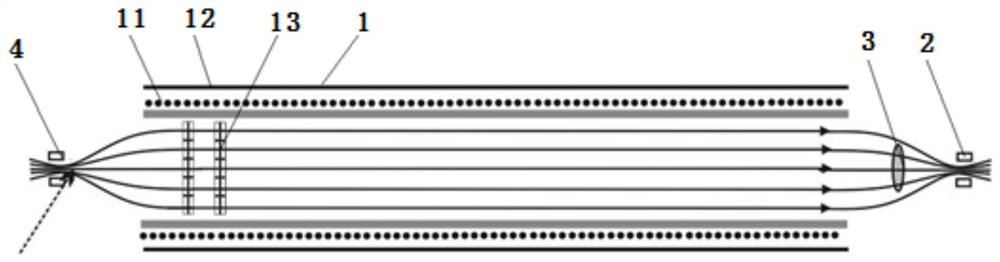
[0068] Such as image 3 As shown, the structure of the magnetic focusing flight tube provided by this embodiment is basically the same as that of Embodiment 2, except that the entrance strong magnet 4 and the exit strong magnet 2 are electromagnets;

[0069] Specifically: in the present embodiment, the entrance strong magnet 4 is an electromagnet, and the electromagnet is a hollow cylindrical coil, so the magnetic induction intensity is the highest at its axis, and the axis of the electromagnet is aligned with the particle generation area to be measured, and the electromagnet generates The magnetic induction intensity is on the order of hundreds of milliTesla to several Tesla. The advantage of using an electromagnet is that it reduces the electrons or ions colliding with the surface of the permanent magnet and re-ionizes to generate secondary electrons or ions, because these particles to be measured will enter the main body of the flight tube and be collected by the particle d...


PUM


Abstract

The invention discloses a magnetic focusing flight tube and a magnetic focusing time-of-flight spectrometer, which include a flight tube main body, an outlet strong magnet and a particle detector; the flight tube main body, the outlet strong magnet and the particle detector are all located in a vacuum chamber ; The exit rear end of the main body of the flight tube is provided with a particle detector and an exit strong magnet in turn; the exit strong magnet is used to concentrate the particles to be measured to be received by the particle detector; the S pole of the exit strong magnet faces the exit of the flight tube main body, are electrons; or, the N pole of the exit strong magnet faces the exit of the main body of the flight tube, and the particles to be measured are ions. The collection efficiency of the flight tube for electrons or ions, when the flight tube is applied to a time-of-flight spectrometer, can obtain the kinetic energy or momentum measurement results of electrons and ions more accurately.

Description

technical field [0001] The invention relates to a flight tube, in particular to a magnetic focusing flight tube and a magnetic focusing time-of-flight spectrometer. Background technique [0002] The time-of-flight spectrometer is mainly used to measure the energy or momentum of electrons or ions excited by photoionization. Its principle is to convert the kinetic energy or momentum of charged particles by measuring the time required to fly a certain distance. For example: in the attosecond pulse measurement technology, the attosecond streak camera is a special device for measuring the pulse width and phase of the attosecond pulse, and its core component is the time-of-flight spectrometer, which is used to measure the action of the attosecond pulse on The energy spectrum of photoelectrons ionized on the target. [0003] In the field of atomic and molecular physics, using cold target recoil ion momentum imaging spectrometer (COLTRIMS) to conduct coincidence measurement (Coinci...

Claims


Application Information

Patent Timeline
Patent Type & Authority Patents(China)
IPC IPC(8): H01J49/06H01J49/20H01J49/40
CPCH01J49/06H01J49/20H01J49/401
Inventor 王向林徐鹏王屹山袁浩王娜娜白永林
Owner XI'AN INST OF OPTICS & FINE MECHANICS - CHINESE ACAD OF SCI
Why Eureka
Try Eureka