Device and method for testing dynamic tensile-shear mechanical properties of solid material in high-temperature environment
A solid material, high temperature environment technology, applied in the field of experimental devices, can solve problems such as inability to carry out experimental research on mechanical properties, inability to carry out dynamic tensile shear experiments at high temperatures, etc., to solve the effect of tension eccentricity, saving space and cost, and avoiding breakage
- Summary
- Abstract
- Description
- Claims
- Application Information
AI Technical Summary
Problems solved by technology
Method used
Image
Examples
specific Embodiment 1
[0079] In this example, a high-temperature dynamic shear experiment of sandstone with a normal tensile stress of 1.5 MPa at 200° C. is carried out.
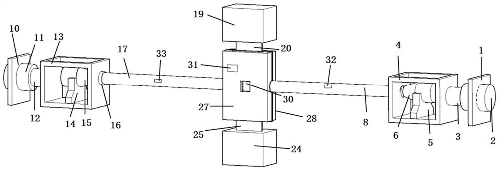
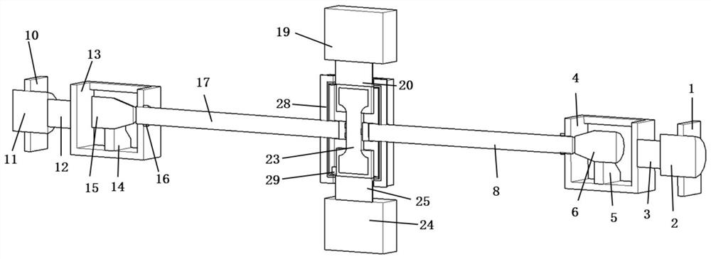
[0080] First, install the right dynamic and static combined loading mechanism. The right static loading cylinder base 1 is placed at the far right end of the device, the right static loading cylinder 2 is fixedly placed on the right static loading cylinder base 1, and the right static loading piston 3 is the right side. The hydraulic actuating mechanism of the static loading oil cylinder 2, its left end face and the right end face of the right loading frame 4 are freely attached, and the right dynamic loading electromagnetic pulse transmitter base 5 and the right dynamic loading electromagnetic pulse transmitter 6 are placed on the right side for loading Inside the frame 4, and can move left and right along the axis of the loading rod, place the right loading rod 8 of TC21 titanium alloy material with a length of 2000 mm and a dia...
specific Embodiment 2
[0089] In this example, a high-temperature dynamic shear experiment of rock with a normal tensile prestress of 2 MPa and an axial shear pre-stress of 5 MPa at 150°C is performed.
[0090] First, install the right dynamic and static combined loading mechanism. The right static loading cylinder base 1 is placed at the far right end of the device, the right static loading cylinder 2 is fixedly placed on the right static loading cylinder base 1, and the right static loading piston 3 is the right side. The hydraulic actuating mechanism on the left side of the static loading cylinder 2, the left end face of which is freely attached to the right end face of the right loading frame 4, and the base 5 of the right dynamic loading electromagnetic pulse transmitter and the right dynamic loading electromagnetic pulse transmitter 6 from right to The left side is placed inside the right side loading frame 4 and can be moved left and right along the axis of the loading rod. The right side load...
PUM
 Abstract
Description
Claims
Application Information
 - R&D
- Intellectual Property
- Life Sciences
- Materials
- Tech Scout
- Unparalleled Data Quality
- Higher Quality Content
- 60% Fewer Hallucinations
Browse by: Latest US Patents, China's latest patents, Technical Efficacy Thesaurus, Application Domain, Technology Topic, Popular Technical Reports.
© 2025 PatSnap. All rights reserved.Legal|Privacy policy|Modern Slavery Act Transparency Statement|Sitemap|About US| Contact US: help@patsnap.com


