Quartered lens for laser beam shaping and laser beam shaping system and method

A laser beam and lens technology, applied in the laser field, can solve the problems of high processing cost, low processing efficiency, and inability to strengthen with laser shock, and achieve the effect of low cost, high laser peak power density, and easy promotion and use

Pending Publication Date: 2022-05-27
AVIC BEIJING AERONAUTICAL MFG TECH RES INST
View PDF0 Cites 0 Cited by
  • Summary
  • Abstract
  • Description
  • Claims
  • Application Information

AI Technical Summary

Problems solved by technology

The disadvantage of the current method is that part of the energy will be lost by using the mask. For the laser processing technology that requires large energy such as laser shock peening, the mask not only produces energy loss, but also reduces the processing efficiency. Obviously, the use of the mask is not a good way.
The special integrating mirror has dozens or even hundreds of processing surfaces, the processing cost is very high, and it is easy to be damaged by strong laser
For example, the peak power density of the π shaping mirror is only 200MW / cm 2 , the shaping mirror cannot be used for laser shock strengthening and other peak power densities greater than 1GW / cm 2 laser processing technology
In addition, the price of the plastic mirror is very expensive, so there are great limitations in the use of this plastic mirror

Method used


Image

  • Quartered lens for laser beam shaping and laser beam shaping system and method
  • Quartered lens for laser beam shaping and laser beam shaping system and method
  • Quartered lens for laser beam shaping and laser beam shaping system and method

Examples


Embodiment Construction

[0022] The embodiments of the present invention will be described in further detail below with reference to the accompanying drawings and examples. The detailed description of the following embodiments and the accompanying drawings are used to exemplify the principles of the present invention, but not to limit the scope of the present invention, that is, the present invention is not limited to the described embodiments without departing from the spirit of the present invention. Any modifications, substitutions and improvements to parts, assemblies and connections are covered under.

[0023] It should be noted that the embodiments in the present application and the features of the embodiments may be combined with each other in the case of no conflict. The present application will be described in detail below with reference to the accompanying drawings and in conjunction with the embodiments.

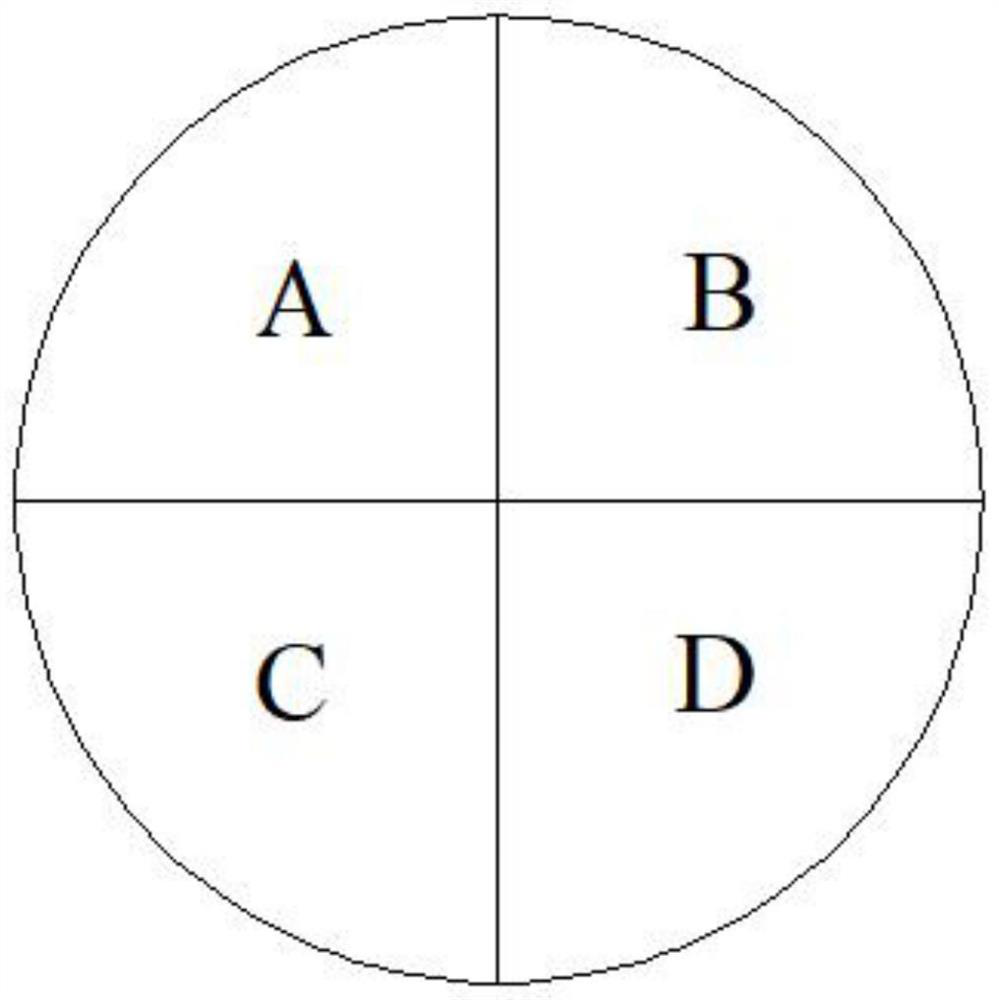
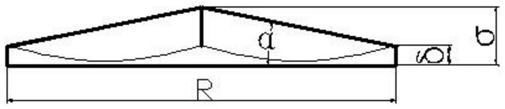
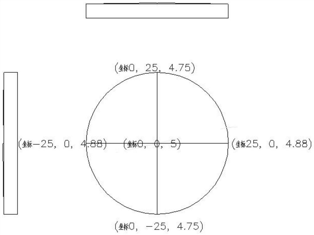
[0024] see figure 1 , 2 , a quadruple lens for laser beam shaping provided by an e...


PUM

PropertyMeasurementUnit
radiusaaaaaaaaaa
aspect ratioaaaaaaaaaa
reflectanceaaaaaaaaaa

Abstract

The invention discloses a quartered lens for laser beam shaping and a laser beam shaping system and method.The quartered lens is provided with a disc-shaped base body with the radius being R and the thickness being sigma, the bottom face of the quartered lens is a plane, the upper surface of the quartered lens is a rectangular pyramid composed of four fan-shaped faces, the lengths of the four ridge lines of the rectangular pyramid are equal, the included angles between the first ridge line and the bottom face and between the second ridge line and the bottom face are both alpha, the included angles between the other third ridge line and the bottom face and between the other fourth ridge line and the bottom face are both kalpha, k is the ratio of the long axis to the short axis of the oval light spot passing through the quartered lens, and the rectangular light spot with the length-width ratio k (k = 1.4-3) can be obtained through the method. The laser energy is not lost, the borne laser peak power density is higher than 3GW / cm < 2 >, the cost is low, and popularization and application are facilitated.

Description

technical field [0001] The invention belongs to laser technology and relates to beam shaping of laser beams. Background technique [0002] Because the circular laser crystal is easy to grow and the pump is uniform, the output of most lasers at present is a circular spot with a Gaussian distribution. For processes such as heat treatment and laser shock treatment, a square light spot needs to be used to meet various process requirements. In the prior art, methods such as masks and special integrator mirrors are generally used to obtain square light spots. The disadvantage of the current method is: the use of a mask will lose part of the energy. For laser processing technologies such as laser shock strengthening that require large energy, the mask not only produces energy loss, but also reduces the processing efficiency. Obviously, using a mask is not a good method. . Special integrator mirrors have dozens or even hundreds of processing surfaces, which are expensive to proces...

Claims


Application Information

Patent Timeline
Patent Type & Authority Applications(China)
IPC IPC(8): G02B27/09G02B3/00
CPCG02B27/0961G02B27/0927G02B3/0056
Inventor 邹世坤曹子文车志刚吴俊峰
Owner AVIC BEIJING AERONAUTICAL MFG TECH RES INST
Why Eureka
Try Eureka