Laser processing method and laser processing system

A laser processing method and laser processing technology, applied in laser welding equipment, metal processing equipment, manufacturing tools, etc., can solve problems such as low efficiency and limited laser focal depth

Active Publication Date: 2016-09-07
张立国
View PDF7 Cites 0 Cited by
  • Summary
  • Abstract
  • Description
  • Claims
  • Application Information

AI Technical Summary

Problems solved by technology

However, due to the limited depth of focus of the laser for each cut, the efficiency of each cut is still not high

Method used


Image

  • Laser processing method and laser processing system
  • Laser processing method and laser processing system
  • Laser processing method and laser processing system

Examples


Embodiment 1

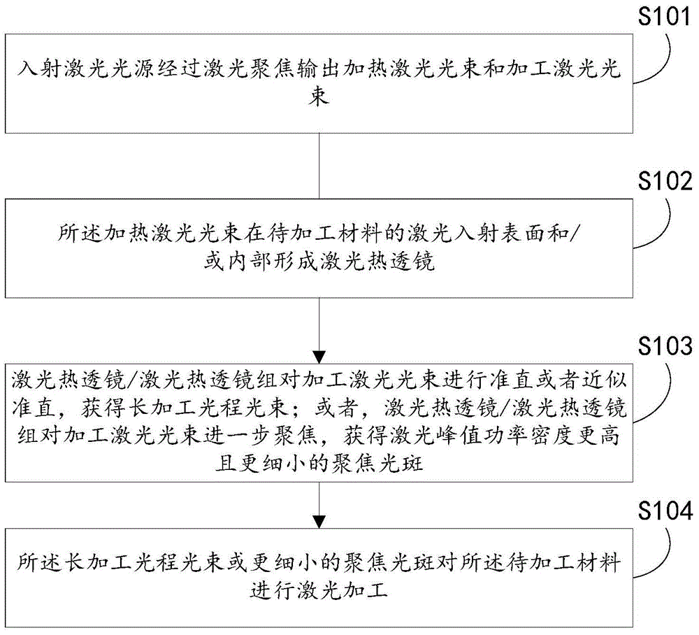
[0038] Embodiment 1, a kind of laser processing method, combine below figure 1 The method provided in this embodiment will be described in detail.

[0039] figure 1 In S101, the incident laser light source outputs a heating laser beam and a processing laser beam through laser focusing.

[0040] Specifically, see figure 2 and image 3 , when it is necessary to carry out laser processing on the material 8 to be processed, a laser focusing module 2 is arranged at a certain distance (along the incident direction of the laser light source) of the material 8 to be processed, for example, when the laser light source is incident from above the material 8 to be processed, then A laser focusing module 2 is set at a certain distance above the material 8 to be processed; Among them, the material 8 to be processed can be sapphire, glass, silicon wafer, quartz or transparent plastic, etc.; the laser focusing module 2 can be focused by a single lens, can also be focused by a multi-lens,...

Embodiment 2

[0048] Embodiment 2. A method for laser processing sapphire scribing. Combine below figure 2 The method provided in this embodiment will be described in detail.

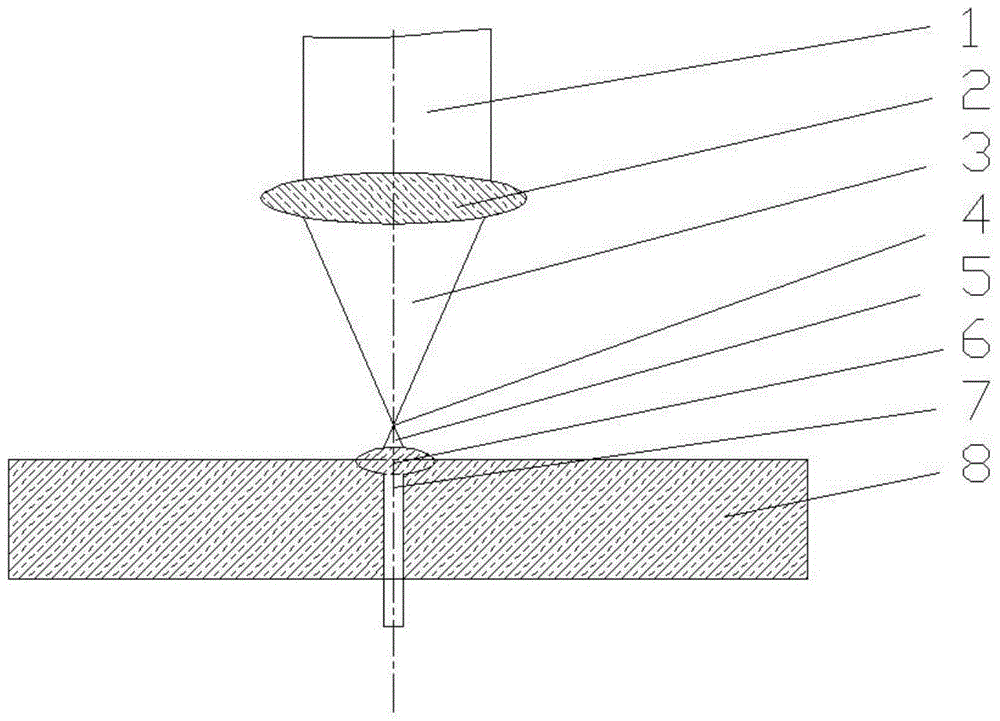
[0049] see figure 2 , figure 2 The heating laser beam is not marked in , and the heating laser beam and the processing laser beam 1 can be the same or different laser light sources, for example, the transmission parameters of the beams are different, the wavelength is different, or the laser pulse width is different. The heating laser beam is also focused by the laser focusing module 2 , the cross section of the focused spot is a solid circle, and a laser focusing thermal lens 6 is formed on the laser incident surface and / or inside of the material 8 to be processed. In this embodiment, the laser focusing thermal lens 6 is formed on the laser incident surface of the material 8 to be processed, and the convex lens surface of the laser focusing thermal lens 6 is formed due to thermal stress.

[0050] The laser fo...

Embodiment 3

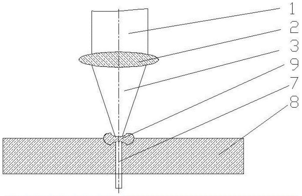
[0056] Embodiment 3. A method of laser processing the glass sheet of the touch screen. Combine below image 3 and Figure 4 The method provided in this embodiment is described in detail.

[0057] see image 3 , image 3 The heating laser beam is not marked in , and the heating laser beam can be the same or different laser light source as the processing laser beam 1, for example, the beam transmission parameters are different, the wavelength is different, or the laser pulse width is different. The heating laser beam is also focused by the laser focusing module 2, and the heating laser beam is focused into a hollow ring with a spot section, see Figure 4 , 29 is a low laser energy or no laser energy area, 28 is a high laser energy area, high laser energy and low laser energy are relative terms. The heating laser beam forms a laser radiation heat dissipation lens 9 on the laser incident surface and / or inside of the material to be processed 8. Radiation heat sink lens 9 conc...


PUM

PropertyMeasurementUnit
thicknessaaaaaaaaaa
thicknessaaaaaaaaaa

Abstract

The invention discloses a laser machining method and system. The laser machining method comprises outputting heating laser beams and machining laser beams from an incident laser light source through laser focusing; forming a laser thermal lens or a laser thermal lens group on the laser incident surface of materials to be machined and or inside the materials to be machined through the heating laser beams; performing collimation or similar collimation on the machining laser beams through the laser thermal lens or the laser thermal lens group to obtain the long machining optical path length beams or performing further focusing on the machining laser beams through the laser thermal lens or the laser thermal lens group to obtain high laser peak power density of small focusing light spots; performing laser machining on the materials to be machined through the long machining optical path length beams or the focusing light spots. According to the laser machining method, the long machining optical path length beams in comparison with the traditional laser focal depth or the high laser peak power density of small focusing light spots can be obtained through the thermal lens effect and the laser machining method is suitable for machining of thick transparent or partially-transparent hard brittle materials.

Description

technical field [0001] The invention relates to the technical field of laser processing, in particular to a laser processing method and a laser processing system. Background technique [0002] At present, for laser processing of brittle and hard materials, there are mainly the following methods: cutting from the laser incident surface to the laser exit surface, cutting from the laser exit surface to the incident surface, and cutting from the inside of the material to be cut. However, due to the limited depth of focus of the laser for each cut, the efficiency of each cut is still not high. Contents of the invention [0003] The technical problem to be solved by the present invention is to provide a laser processing method and a laser processing system, which can obtain a laser processing optical path longer than a traditional laser focal depth or a smaller laser focus spot, which is suitable for processing thicker or laser damage thresholds. Transparent or partially transp...

Claims


Application Information

Patent Timeline
Patent Type & Authority Patents(China)
IPC IPC(8): B23K26/38B23K26/064
CPCB23K26/0648B23K26/38
Inventor 张立国
Owner 张立国
Why Eureka
Try Eureka