Unlock instant, AI-driven research and patent intelligence for your innovation.

Stator yoke permanent magnet type dual-modulation motor

A stator yoke, double modulation technology, used in motors, synchronous motors with static armatures and rotating magnets, magnetic circuits, etc., can solve the problem of limited torque capacity improvement, insufficient torque capacity, permanent magnet There are many problems such as magnetic leakage, which can improve the torque output capacity, enrich the working harmonics, and utilize the design space.

Pending Publication Date: 2022-05-27
ANHUI UNIVERSITY +1
View PDF0 Cites 0 Cited by
  • Summary
  • Abstract
  • Description
  • Claims
  • Application Information

AI Technical Summary

Problems solved by technology

However, the traditional rotor and stator permanent magnet field modulation motors have many problems such as permanent magnet flux leakage and limited torque capacity improvement, so that the torque capacity cannot be fully explored.

Method used


Image

  • Stator yoke permanent magnet type dual-modulation motor
  • Stator yoke permanent magnet type dual-modulation motor
  • Stator yoke permanent magnet type dual-modulation motor

Examples


Embodiment 1

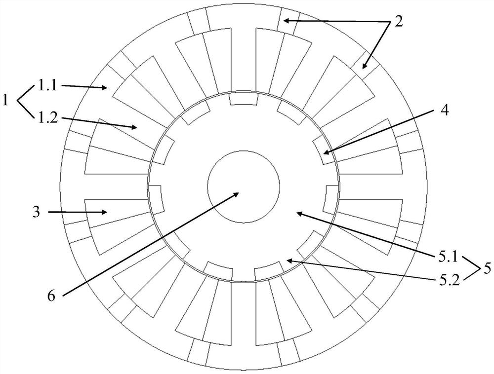
[0027] See Figure 1 As shown, the present invention is a stator yoke permanent magnet type dual modulation motor, comprising a stator 1, stator permanent magnet 2, armature winding 3, rotor permanent magnet 4, rotor 5 and hinge 6; the inner ring of stator 1 is provided with rotor 5, rotor 5 is provided with a mounting hole compatible with the rotor 6, stator 1 is provided with a stator permanent magnet 2, the stator permanent magnet 2 ring array is provided with a plurality, and located at the outer ring of stator 1, the stator permanent magnet 2 is in the opposite direction of magnetization; rotor 5 is provided with rotor permanent magnet 4, The rotor permanent magnet 4 ring array is provided with multiple and is located at the outer ring of rotor 5, and the rotor permanent magnet 4 is charged in the same direction;

[0028] Among them, stator 1 includes the stator yoke 1.1 and stator teeth 1.2, the inner ring ring ring array of the stator yoke 1.1 is provided with multiple stato...

Embodiment 2

[0033] combine Figure 2 and Figure 3 As shown, the operating principle of the stator yoke permanent magnet type dual modulation motor involved in the present embodiment is: at the rotor position θ = 0 ° (electrical angle), the magnetic field line starts from the stator permanent magnet 2, passes through the stator 1.1 to the stator tooth 1.2, passes through the rotor permanent magnet 4, and then through the rotor modulation tooth 5.2, forming a closed magnetic circuit, at this time the permanent magnet chain passes through the coil A1, at this time the magnetic chain is the largest; at the rotor position θ = 180 ° (electrical angle), the magnetic field line starts from the stator permanent magnet 2, After reaching the stator yoke 1.1 and entering the stator tooth 1.2, after passing through the rotor modulation tooth 5.2, a closed loop is formed through the adjacent rotor modulation tooth 5.2, at which time the permanent magnet chain penetrates into coil A1, and the magnetic chain ...


PUM


Abstract

The invention discloses a stator yoke permanent magnet type dual-modulation motor which comprises a stator, stator permanent magnets, rotor permanent magnets, a rotor and a rotating shaft. A rotor is arranged on the inner ring of the stator, and a mounting hole matched with the rotating shaft is formed in the rotor; stator permanent magnets with opposite magnetizing directions are arranged in a stator yoke of the stator, rotor permanent magnets are uniformly embedded in the rotor and have the same magnetizing direction, a cavity is formed between the stator yoke and stator teeth and is used for arranging a three-phase armature winding, and a cavity is formed between the stator yoke and the stator teeth and is used for arranging the three-phase armature winding; according to the motor, a traditional stator yoke permanent magnet motor and a rotor consequent pole permanent magnet motor are combined, the stator yoke permanent magnet type double-modulation motor is formed on the basis of inheriting and fusing the advantages of respective original motors, the air gap magnetic field modulation effect is achieved, and the torque output capacity of the motor can be further improved.

Description

Technical field [0001] The present invention relates to the field of motor technology, specifically to a stator yoke permanent magnet type dual modulation motor. Background [0002] In 1957, the American General Electric Company G. Kronacher first proposed a fixed-rotor multi-tooth structure reluctance motor, and named the cursor motor, its significant features are: the position of the air gap magnetic conduction axis changes significantly when the rotor moves slightly, which in turn causes a large change in the magnetic field distribution. With its simple structure and low torque ripple, the cursor motor has been applied in low-power occasions such as money counters and fax machines. However, due to the relatively low torque density and power factor of the motor, which hinders its further industrial applications, the research on this magnetoresistive motor based on the principle of magnetic field modulation has stalled. In 1999, Professor T.A. Lipo of the University of Wisconsin...

Claims


Application Information

Patent Timeline
IPC IPC(8): H02K21/14H02K1/17H02K1/276
CPCH02K21/14H02K1/17H02K1/276Y02T10/64H02K1/2746
Inventor 李亚金岱晨丁石川杭俊李伟
Owner ANHUI UNIVERSITY