Visual test display system

A display system and visual technology, applied in the field of visual testing, can solve the problems such as the inability to reflect the stereoscopic visual effect of the human eye and the complicated visual testing process, and achieve the effect of accurate parallax value and improved parameter accuracy and speed.

Active Publication Date: 2022-05-27
深圳市微特精密科技股份有限公司
View PDF4 Cites 0 Cited by
  • Summary
  • Abstract
  • Description
  • Claims
  • Application Information

AI Technical Summary

Problems solved by technology

[0003] The invention provides a visual test and display system, which is used to solve the situation that the stereoscopic visual effect of human eyes cannot be reflected and the visual test process is complicated

Method used


Image

  • Visual test display system
  • Visual test display system
  • Visual test display system

Examples


Embodiment 1

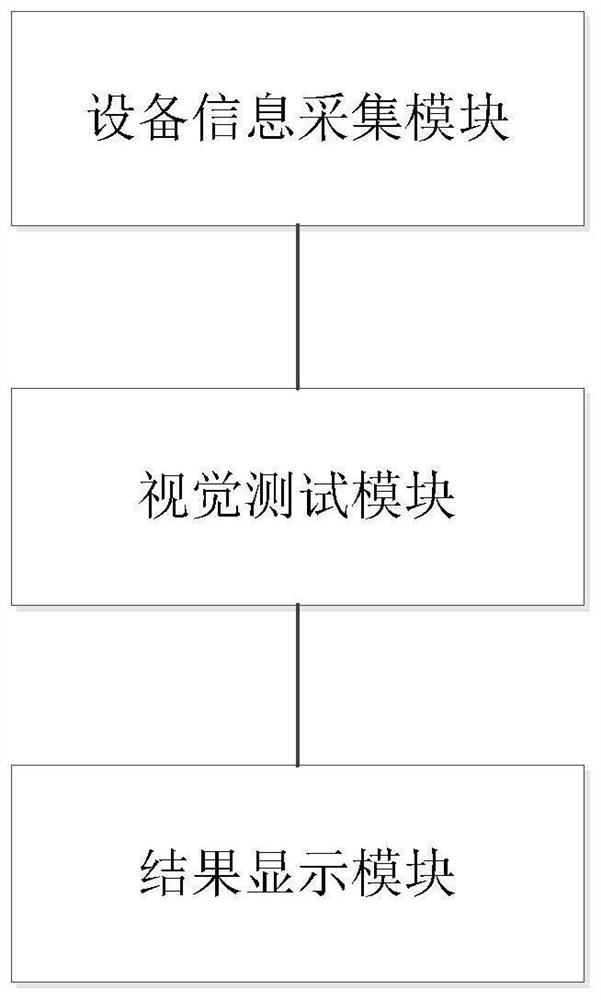
[0072] as attached figure 1 As shown, an embodiment of the present invention provides a visual test display system, including:

[0073] Device information collection module: used to collect parameter information of the target display device, and generate a corresponding retrieval code according to the parameter information;

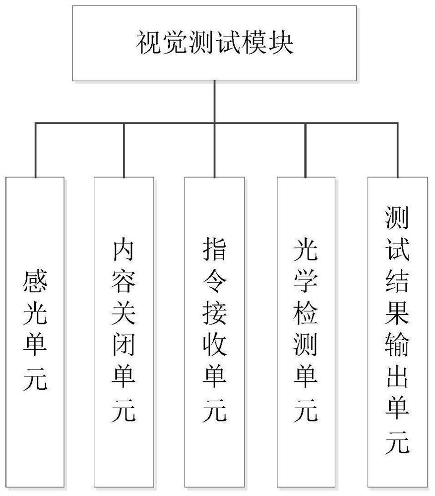
[0074] Visual test module: used to obtain visual test items based on the preset content database according to the retrieval code, perform visual tests, and output test results;

[0075] Result display module: used to perform digital analysis on the test results, obtain the analysis results, visualize the analysis results, and obtain graphical test results;

[0076] The working principle of the above technical solution is as follows: in the prior art of the present invention, when performing visual tests on different devices, all display devices adopt the same test items and test procedures, and do not carry out individualized tests according to different...

Embodiment 2

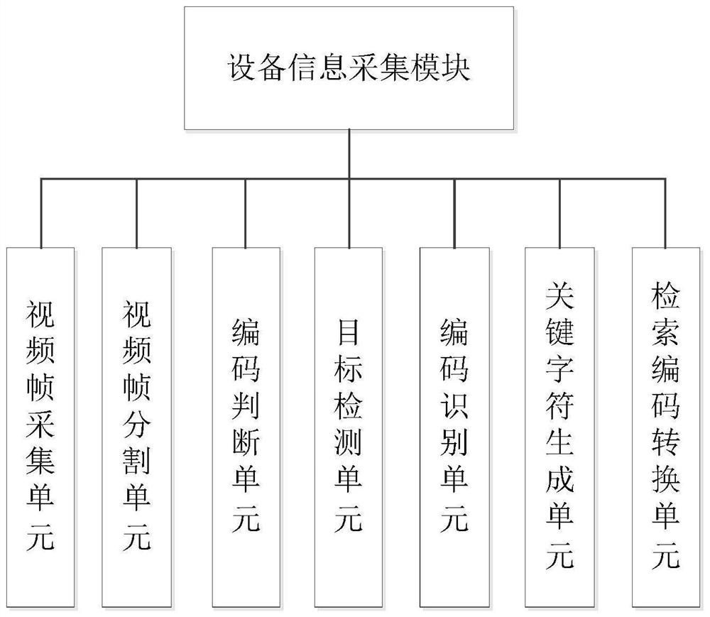
[0079] In an embodiment of the present invention: as attached figure 2 As shown, the device information collection module includes:

[0080] Video frame acquisition unit: used to collect video frame data of the target display device in the environment with a depth camera;

[0081] Video frame segmentation unit: for segmenting the video frame data of the target display device to obtain several frames of image data;

[0082] coding judgment unit: for judging whether there is an identification code corresponding to the target display device in the image data based on the image data;

[0083] Target detection unit: when there is no identification code corresponding to the target display device in the image data, perform edge detection on each frame of image data, obtain the depth information corresponding to the target display device, and display according to the target The depth information of the device, and the parameter information corresponding to the target display device...

Embodiment 3

[0090] In an embodiment of the present invention: the target detection unit includes:

[0091] Pixel grid numbering subunit: used to obtain the pixel grid of the image data, and number the pixel grid according to the preset sorting method, and obtain the pixel grid number value of each frame of image;

[0092]Pixel grid comparison subunit: used to obtain adjacent frame image data, and perform pixel difference comparison according to the pixel grid number in the corresponding image data to determine pixel difference data between adjacent frame image data;

[0093] Parallax acquisition subunit: used to acquire the parallax value between adjacent frame images according to the pixel difference data between the adjacent frame image data;

[0094] Matrix decomposition subunit: used to perform matrix decomposition on the disparity values ​​between the adjacent frame images, and obtain the internal matrix and external parameters corresponding to each frame of image data;

[0095] Dep...


PUM


Abstract

The invention provides a visual test display system, which comprises an equipment information acquisition module used for acquiring parameter information of target display equipment and generating a corresponding retrieval code according to the parameter information; the visual testing module is used for acquiring visual testing items according to the retrieval codes based on a preset content database, performing visual testing and outputting a testing result; and the result display module is used for digitally analyzing the test result to obtain an analysis result, and visualizing the analysis result to obtain a graphical test result. According to the invention, the real visual effect of the human eyes is simulated by adopting the double probes, and the parameters of the display equipment are tested in a binocular stereo manner, so that the output parameters of the display equipment better accord with the visual comfort value of the human eyes.

Description

technical field [0001] The invention relates to the technical field of visual testing, in particular to a visual testing display system. Background technique [0002] At present, when performing visual testing of display devices, the testing process usually requires manual sending of instructions. Secondly, the testing process is limited to measuring optical parameters, and the related parameters of displayed stereo features are less measured, and monocular measurement is mainly used. This method relies on manual or mechanical transmission structure to spatially position the probe, so it does not support the detection of relevant parameters on the 3D display, the operation process is cumbersome, and the process is prone to delay, it is not real-time, and cannot be well reflected. The stereo vision effect of the human eye leads to poor reliability of the final test, such as the paper Yin,Ma,Zhong,etal.SLAM-Based Self-Calibration of a Binocular Stereo Vision Rig in Real-Time[J...

Claims


Application Information

Patent Timeline
Patent Type & Authority Applications(China)
IPC IPC(8): H04N13/106H04N17/04
CPCH04N17/04H04N13/106Y02P90/30
Inventor 孙德滔
Owner 深圳市微特精密科技股份有限公司
Why Eureka
Try Eureka