

Electric industrial vehicle combined power system and control method
An electric industrial vehicle, combined power technology, applied in electric vehicles, electric power units, power units, etc., can solve the problems of reducing system reliability, single effect, simple transmission route, etc. The effect of smoothly adjustable driving force
Pending Publication Date: 2022-05-31
CHINA UNIV OF MINING & TECH
View PDF0 Cites 0 Cited by
- Summary
- Abstract
- Description
- Claims
- Application Information
AI Technical Summary
Problems solved by technology
However, these improvements still fail to make full use of the high-efficiency range of the motor. At the same time, these improvements either use complex power transmission routes to reduce the reliability of the system, or the transmission routes are simple but have a single effect. Optimizing powertrains in the vehicle segment of industrial vehicles
Method used
View moreImage
Smart ImageViewing Examples

Examples
Embodiment 1
Login to View More PUM
 Abstract
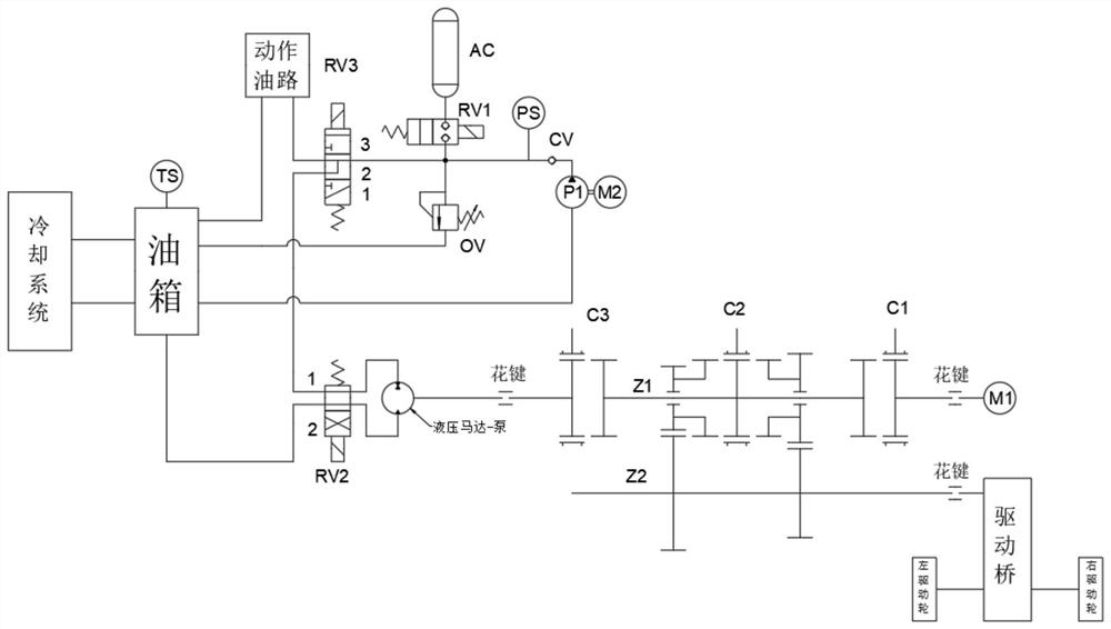
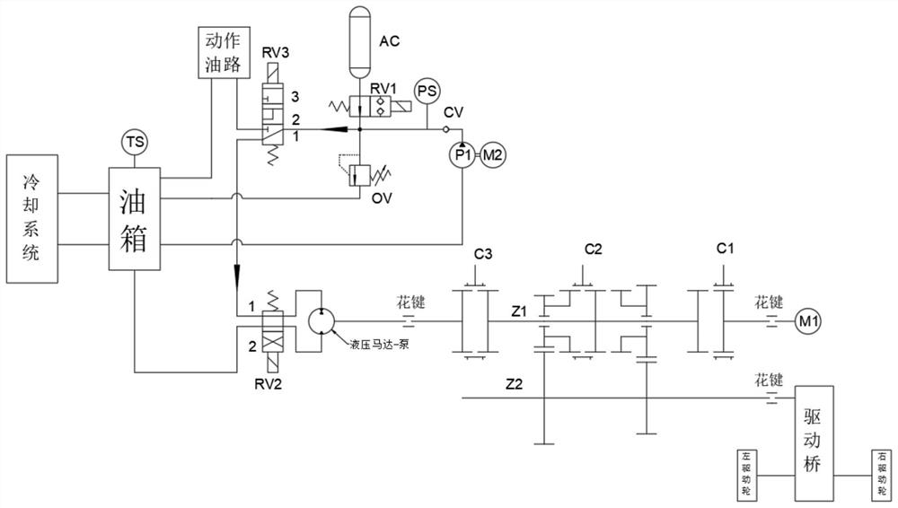
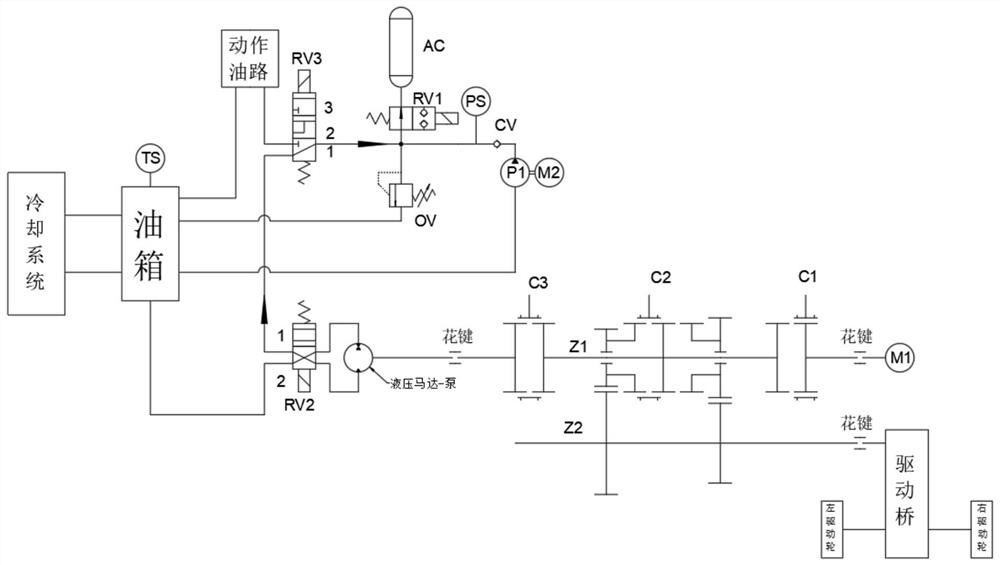
The invention belongs to the technical field of electric industrial vehicles, and particularly relates to a combined power system of an electric industrial vehicle and a control method. The power system comprises a cooling system, an oil tank, a hydraulic power system, a vehicle driving system, an action oil way, a first tooth clutch C1, a second tooth clutch C2, a third tooth clutch C3, a controller, a vehicle speed gear button and a hydraulic execution element speed gear button. The control method aims at six modes including a starting power assisting mode, an auxiliary braking mode, a combined driving mode, a combined hydraulic mode, a limping mode and an independent driving mode, and the control method controls starting and stopping of the six modes and switching among the six modes. According to the control method, full utilization of the working parts is achieved, the number of the used working parts is smaller, the reliability of the vehicle driving system and the hydraulic power system is higher, and more functions can be actually used. The invention aims to optimize a power system in the field of electric industrial vehicles.
Description
A kind of electric industrial vehicle combined power system and control method technical field The invention belongs to the technical field of electric industrial vehicles, and in particular relates to a combined power system of an electric industrial vehicle and a Control Method. Background technique [0002] At present, with the continuous development of the economy and society, the market potential of electric industrial vehicles is huge. The environmental protection, efficiency and reliability of industrial vehicles have higher requirements. Technical roadmap of existing electric industrial vehicle power system solutions There is a single line, and most of them use a single-motor power system or a dual-motor independent power system, which cannot meet the long-term and high-efficiency operation of the motor at the same time. Running and short-term high-power operation cannot make full use of the idle time of the motor. The prior art solution addresses this situat...
Claims
Login to View More Application Information
Patent Timeline
 Patent Type & Authority Applications(China)
IPC IPC(8): B60K1/02B60K17/02B60K17/06B60K17/10B60K11/02B60L15/36
CPCB60K1/02B60K17/02B60K17/06B60K17/10B60K11/02B60L15/36Y02T10/70
Inventor 卢昊苗昀朱真才彭玉兴陈国安汤裕
Owner CHINA UNIV OF MINING & TECH