
Rock pipe-jacking construction method for reducing resistance through underground water buoyancy

A construction method and groundwater technology, applied in hydroelectric power generation, earthwork drilling, pipeline laying and maintenance, etc., can solve the problem that the buoyancy of the pipeline is not fully utilized, the buoyancy of the pipeline cannot be ignored, the contact between the pipe joint and the surrounding rock and the stress situation Insufficient and other problems, to achieve the effect of reducing project cost, reducing resistance and improving construction efficiency

Active Publication Date: 2022-05-31
CHONGQING UNIV
View PDF9 Cites 0 Cited by
  • Summary
  • Abstract
  • Description
  • Claims
  • Application Information

AI Technical Summary

Problems solved by technology

In water-rich rock formations, due to environmental protection requirements, groundwater is not allowed to be discharged at will, and must be discharged after treatment at the originating end. Groundwater will accumulate in the over-excavation gap, and its buoyancy to the pipeline cannot be ignored; In the existing pipe jacking construction technology, there is insufficient research on the contact between the pipe joint and the surrounding rock under the influence of the buoyancy of the groundwater in rock formations and the stress situation, and the buoyancy of the groundwater to the pipeline has not been fully utilized.

Method used


Image

  • Rock pipe-jacking construction method for reducing resistance through underground water buoyancy
  • Rock pipe-jacking construction method for reducing resistance through underground water buoyancy
  • Rock pipe-jacking construction method for reducing resistance through underground water buoyancy

Examples


Embodiment Construction

[0036] Embodiments of the technical solutions of the present invention will be described in detail below with reference to the accompanying drawings. The following examples are only used to more clearly illustrate the technical solutions of the present invention, and are therefore only used as examples, and cannot be used to limit the protection scope of the present invention. It should be noted that, unless otherwise specified, the technical or scientific terms used in this application should have the usual meanings understood by those skilled in the art to which the present invention belongs.

[0037] In the description of the present application, it should be understood that the terms "first", "second", etc. are only used for description purposes, and cannot be interpreted as indicating or implying relative importance or implying the number of indicated technical features . In the description of the present invention, "plurality" means two or more, unless otherwise express...


PUM


Abstract

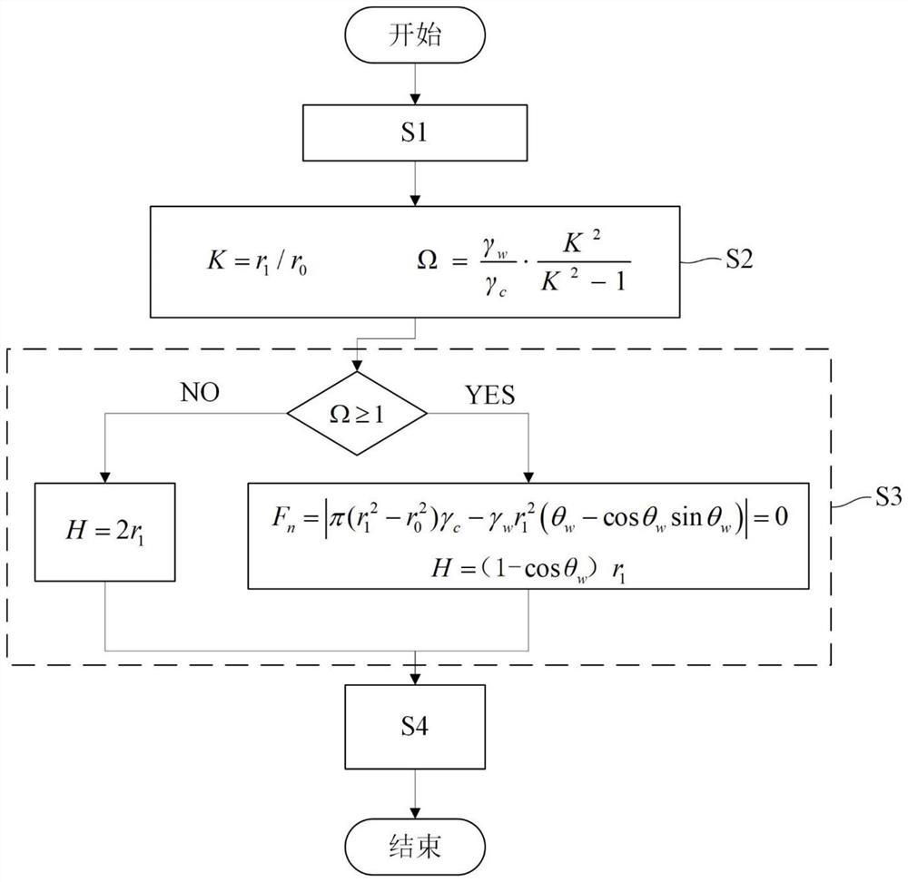
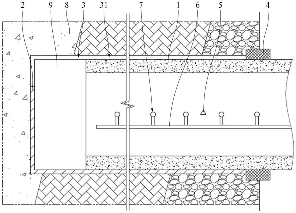
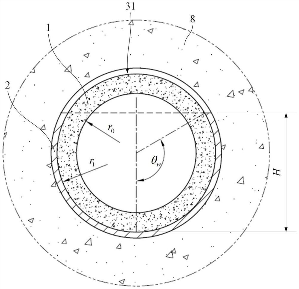
The invention relates to the technical field of pipe-jacking tunnel engineering, and discloses a rock pipe-jacking construction method for reducing resistance through underground water buoyancy. The method comprises the following steps: S1, acquiring engineering parameters required for calculating the contact pressure of a pipe joint; s2, calculating a buoyancy index omega according to the engineering parameters, wherein the buoyancy index omega is the ratio of the maximum buoyancy of underground water in the over-excavation gap of the pipe-jacking tunnel to the pipe joint to the dead weight of the pipe joint; s3, pipe jacking projects are classified according to the obtained buoyancy index omega, and the optimal water level height H of underground water in the overexcavation gap is calculated; s4, jacking operation is conducted, specifically, a pipe jacking tunnel is excavated through a jacking machine, and pipe joints are jacked; in the pipe joint jacking process, the pipe joints are kept in sealed connection, the pipe joints and the jacking machine head are kept in sealed connection, and the pipe joints and a pipe jacking tunnel opening are kept in sealed connection; and the water level in the over-excavation gap outside the pipe joint is controlled, so that the water level in the over-excavation gap is equal to or close to the optimal water level height H. The pipe joint jacking resistance can be reduced, so that the limit jacking distance of pipe jacking construction is increased.

Description

technical field [0001] The invention relates to the technical field of pipe jacking tunnel engineering, in particular to a rock pipe jacking construction method utilizing groundwater buoyancy to reduce drag. Background technique [0002] The pipe jacking method is a non-excavation type pipeline laying construction technology, which has the advantages of small excavation disturbance, fast tunneling speed, and low safety risk. It is widely used in underground water pipelines, natural gas and oil pipelines, communication cables, etc. Construction of pipelines. [0003] Jacking resistance is a key factor affecting the selection of jacking equipment, pipe section structure design, relay layout and ultimate jacking length. Frictional resistance is the main component of jacking resistance in long-distance pipe jacking projects. In practical engineering, measures such as over-excavation are usually taken to reduce the frictional resistance between the outer wall of the pipe and the...

Claims


Application Information

Patent Timeline
Patent Type & Authority Applications(China)
IPC IPC(8): E21D9/00F16L1/036
CPCE21D9/00E21D9/003F16L1/036Y02E10/20
Inventor 钟祖良刁小军刘东双
Owner CHONGQING UNIV
Learn More