
Time-varying gain circuit

A time-varying gain and circuit technology, applied in the direction of gain control, electrical components, amplification control, etc.

Pending Publication Date: 2022-05-31
SHANXI FENXI HEAVY IND
View PDF0 Cites 0 Cited by
  • Summary
  • Abstract
  • Description
  • Claims
  • Application Information

AI Technical Summary

Problems solved by technology

[0007] In summary, how to solve the design problem of time-varying gain circuits with different frequencies, low noise, low power consumption, low voltage, and continuous gain changes in the active sonar detection technology in the prior art has become an urgent need for those skilled in the art. solved problem

Method used


Image

  • Time-varying gain circuit

Examples


Embodiment Construction

[0028] In order to make the object, technical solution and advantages of the present invention clearer, the implementation manner of the present invention will be further described in detail below in conjunction with the accompanying drawings.

[0029] In addition, in the description of the present invention, the terms "longitudinal", "transverse", "upper", "lower", "front", "rear", "left", "right", "vertical", "horizontal" The orientations or positional relationships indicated by , "top", "bottom", etc. are based on the orientations or positional relationships shown in the drawings, and are only for the convenience of describing the present invention and do not require that the present invention must be constructed and operated in a specific orientation, and therefore cannot be construed as a limitation of the invention. The terms "connected" and "connected" used in the present invention should be understood in a broad sense, for example, it can be fixedly connected or detach...


PUM


Abstract

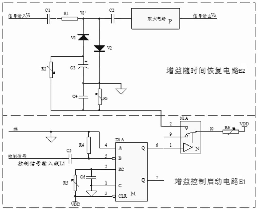
The invention provides a time-varying gain circuit which comprises a gain control starting circuit and a time-dependent gain recovery circuit, the gain control starting circuit is connected with the time-dependent gain recovery circuit through electric signals, the time-varying gain circuit is low in noise and power consumption, the gain of the time-varying gain circuit changes continuously, and meanwhile the time-varying gain circuit is not limited by power supply voltage. The time-varying gain circuit solves the design problem of the time-varying gain circuit which requires low noise, low power consumption, low voltage and continuous gain change at different frequencies in the existing active sonar detection technology, and has important research significance and use value. The method has important research significance and use value.

Description

technical field [0001] The invention belongs to the technical field of integrated circuit design, and more specifically relates to a time-varying gain circuit. Background technique [0002] The time-varying gain amplifier circuit simply means that the gain of the amplifier circuit is a function of time (distance). Since in the active sonar detection system, the time actually corresponds to the distance of the target from the antenna, from this perspective, in the active sonar detection system, it can be called a distance gain amplifier circuit. [0003] The mechanism of the time-varying gain amplification circuit is to attenuate or amplify the scattered echoes of short-distance targets with a lower gain, and to amplify the scattered echoes of long-distance targets with a higher gain, so that the echo signals entering the data acquisition circuit become relatively stable. Finally, the strong signal of the shallow target echo is attenuated or suppressed, avoiding the saturat...

Claims


Application Information

Patent Timeline
IPC IPC(8): H03G3/20H03G3/30
CPCH03G3/20H03G3/301
Inventor 闫玉花冯耀峰李阳任冬丽白翼虎高慧霞贾晓娟崔剑锋
Owner SHANXI FENXI HEAVY IND
Learn More