Incubation device for aquaculture
A technology for aquaculture and shells, applied in fish farming, climate change adaptation, applications, etc., can solve problems such as inconvenient cleaning, insufficient oxygen, and breeding of bacteria
- Summary
- Abstract
- Description
- Claims
- Application Information
AI Technical Summary
Problems solved by technology
Method used
Image
Examples
Embodiment 1
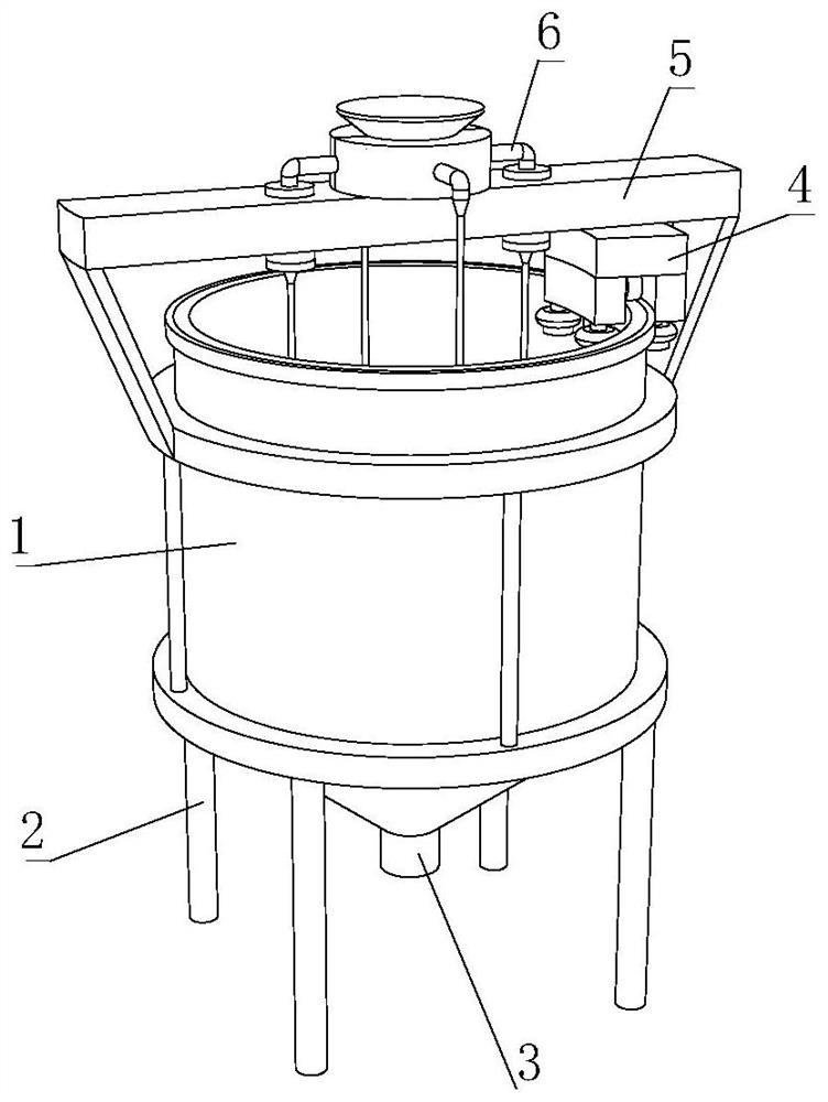
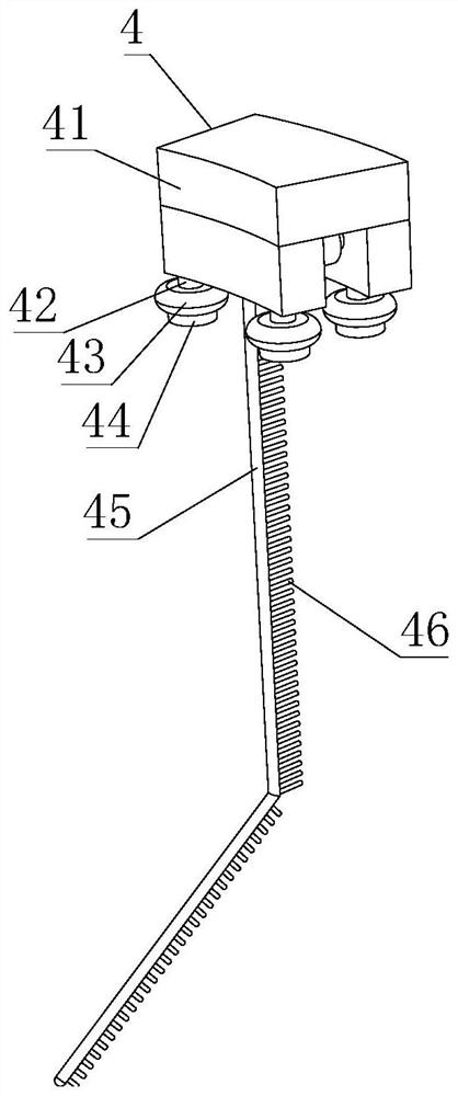
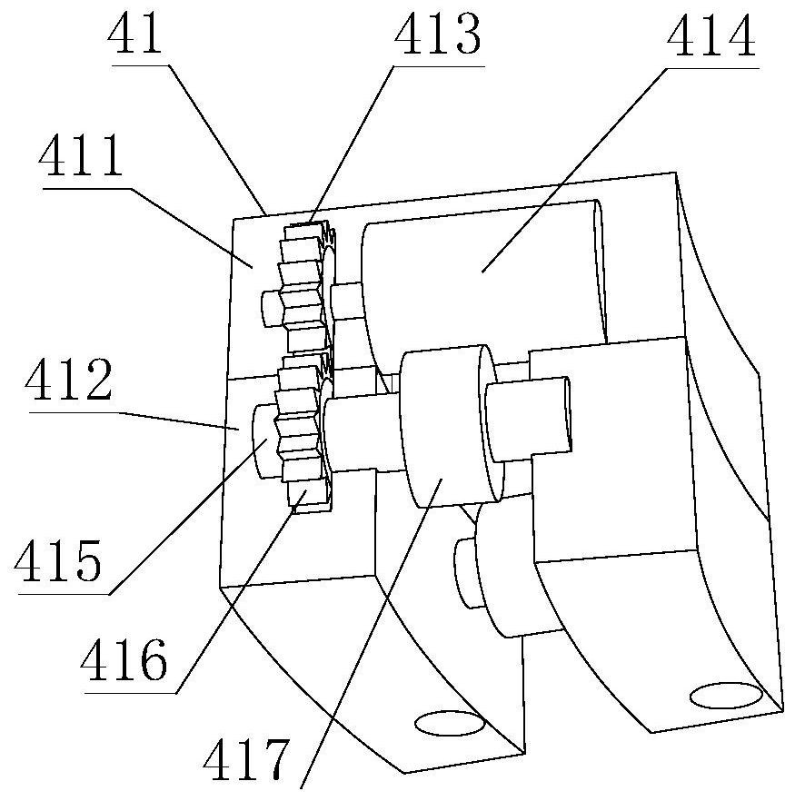
[0035] like Figure 1-6 As shown, the present invention provides an aquaculture hatching device, comprising a hatching cylinder 1, a support column 2 is fixedly connected to the lower side of the hatching cylinder 1, a discharge port 3 is fixedly connected to the lower side of the hatching cylinder 1, A horizontal plate 5 is arranged on the outside, and the upper side of the horizontal plate 5 is fixedly connected with a foaming and oxygenating mechanism 6. The foaming and oxygenating mechanism 6 includes a heating mechanism 66, and the heating mechanism 66 includes a foaming mechanism 668. The foaming mechanism 668 includes a foaming mechanism 668. Tube 6683, the inside of the bubble tube 6683 is provided with a fine hole 6684, the inner wall of the incubation cylinder 1 is movably connected with a mobile cleaning mechanism 4, the mobile cleaning mechanism 4 includes a moving mechanism 41, and the moving mechanism 41 includes a driving gear 413, the interior of the driving gea...
Embodiment 2
[0038] like Figure 1-6 As shown, on the basis of Embodiment 1, the present invention provides a technical solution: preferably, a ring-shaped chamber 6682 is fixedly connected to the upper side of the bubble outlet tube 6683, and a weight ring 6681 is fixedly connected to the upper side of the ring-shaped chamber 6682. , the lower side of the weight ring 6681 is fixedly connected with a rotation button 6685, the inner part of the rotation button 6685 is rotatably connected with a one-way plate 6686, and the upper side of the one-way plate 6686 overlaps with the lower side of the weight ring 6681.
[0039]In this embodiment, air enters into the weight ring 6681 from the rubber tube 667, punches the one-way plate 6686 into the ring-shaped chamber 6682, a part is released from the bottom outlet of the bubble outlet tube 6683 to form large air bubbles, and the other part is released into the weight ring 6681. It is released from the pores 6684 to form small air bubbles, and the t...
Embodiment 3
[0041] like Figure 1-6 As shown, on the basis of Embodiment 1, the present invention provides a technical solution: preferably, a rubber tube 667 is fixedly connected to the upper side of the foaming mechanism 668, and a conical cap 666 is fixedly connected to the upper side of the rubber tube 667, A lower ring cover 665 is fixedly connected to the upper side of the conical cap 666, an electric heating element 669 is fixedly installed on the upper side of the lower ring cover 665, and a heating shell 663 is fixedly connected to the upper side of the lower ring cover 665. The inner wall of the heating shell 663 is fixedly connected, the inside of the electric heating element 669 is fixedly installed with a spiral heating rod 664, the upper side of the heating shell 663 is fixedly connected with an upper ring cover 662, and the upper side of the upper ring cover 662 is fixedly connected with a connecting pipe 661 A turbo fan casing 64 is fixedly installed on one side of the hea...
PUM
 Abstract
Description
Claims
Application Information
 - R&D
- Intellectual Property
- Life Sciences
- Materials
- Tech Scout
- Unparalleled Data Quality
- Higher Quality Content
- 60% Fewer Hallucinations
Browse by: Latest US Patents, China's latest patents, Technical Efficacy Thesaurus, Application Domain, Technology Topic, Popular Technical Reports.
© 2025 PatSnap. All rights reserved.Legal|Privacy policy|Modern Slavery Act Transparency Statement|Sitemap|About US| Contact US: help@patsnap.com


