
Insulation middle layer layer-by-layer coating equipment of heat distribution pipeline

A thermal pipeline and coating technology, which is applied in sustainable buildings and spraying devices, can solve the problems of inconvenient processing rotation, inconvenient control of the stability of processed parts, inconvenient adjustment of the limit of processed parts, etc., to achieve efficient combined installation work, Helping production and processing work, efficiently guiding the effect of production purposes

Pending Publication Date: 2022-06-03
张琴
View PDF3 Cites 3 Cited by
  • Summary
  • Abstract
  • Description
  • Claims
  • Application Information

AI Technical Summary

Problems solved by technology

It is inconvenient to adjust the limit of the workpiece, it is not convenient for the workpiece to be processed and rotated more uniformly, and it is also inconvenient to stabilize the workpiece. Therefore, a layer-by-layer coating equipment for heat pipe insulation is needed , to solve the problems raised in the above

Method used


Image

  • Insulation middle layer layer-by-layer coating equipment of heat distribution pipeline
  • Insulation middle layer layer-by-layer coating equipment of heat distribution pipeline
  • Insulation middle layer layer-by-layer coating equipment of heat distribution pipeline

Examples


Embodiment 1

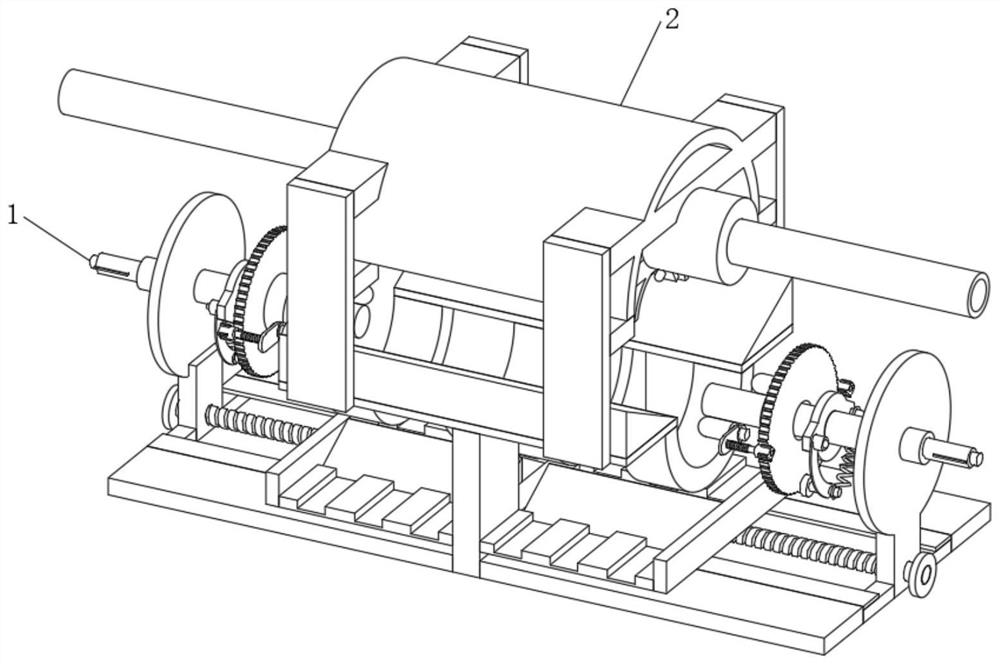
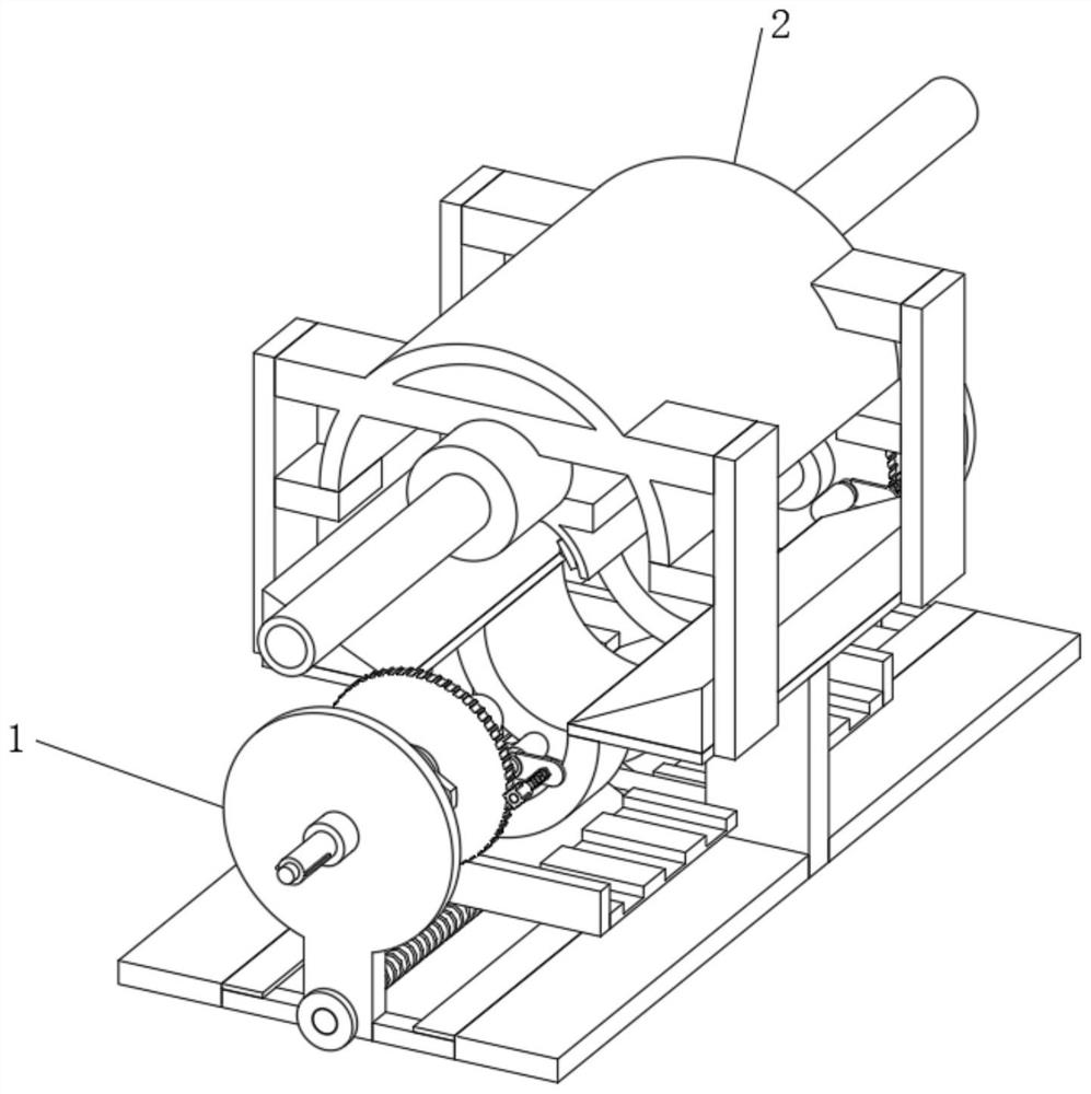
see figure 1 , figure 2 , an embodiment provided by the present invention: a layer-by-layer coating equipment for thermal insulation middle layer of heat pipeline, including a rotary adjustment structure 1 and a coating connection production structure 2, and the upper end position of the rotation adjustment structure 1 is fixedly connected with a coating connection Production structure 2, through the setting of the structure, it is convenient to carry out the production work of the heat pipe;

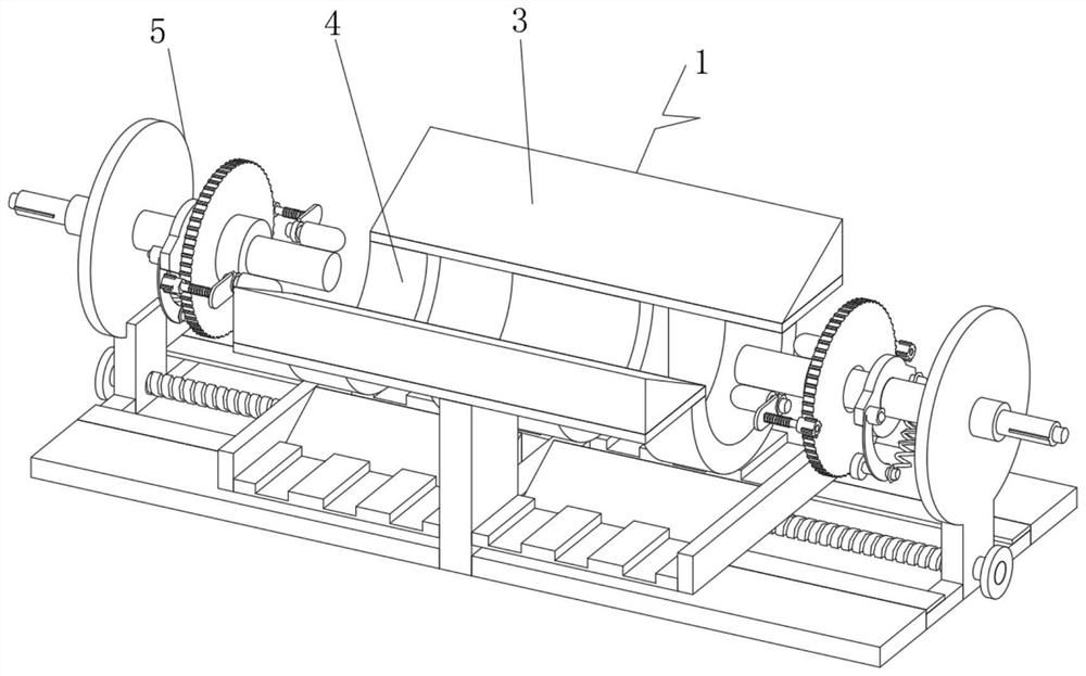
see image 3 , the rotation adjustment structure 1 includes an inclined conduction connecting frame 3, an arc-shaped connecting slot frame 4 and a rotating drive part 5. The inclined conduction connecting frame 3 is arranged at the center position of the inner end of the rotating adjustment structure 1, and the lower end position of the inclined conduction connecting frame 3 The arc-shaped connecting slot frame 4 is fixedly connected, the bottom end position of the inclined conduction ...

Embodiment 2

On the basis of Example 1, as Figure 8 As shown, the side end position of the rotation adjusting structure 1 is communicated with a matching conduction channel tube 23 , and the side end position of the matching conduction channel tube 23 is communicated with a transmission conduit 22 .

[0034] In the implementation of this embodiment, the user installs the transmission conduit 22 and the matching conduction groove pipe 23, and the transmission conduit 22 and the matching conduction groove pipe 23 are connected to the rotating adjustment structure 1, so that the guide and drainage of the excess waste liquid can be realized, and more It is convenient for collection purposes, and the transmission conduit 22 is matched and connected with the communication slot plate 16 by matching the conduction slot tube 23 to achieve efficient combined installation work, achieve efficient guide row production purposes, and better help production and processing work.

[0035] Working principle:...


PUM


Abstract

The invention relates to the technical field of heat distribution pipeline manufacturing equipment, and discloses heat insulation middle layer layer-by-layer coating equipment for a heat distribution pipeline, which comprises a rotary adjusting structure and a coating connection production structure, and the upper end position of the rotary adjusting structure is fixedly connected with the coating connection production structure; the rotation adjusting structure comprises an inclined conduction connecting frame, an arc-shaped connecting groove frame and a rotation driving part, the inclined conduction connecting frame is arranged at the center position of the inner end of the rotation adjusting structure, and the arc-shaped connecting groove frame is fixedly connected to the lower end position of the inclined conduction connecting frame; the bottom end positions of the inclined conduction connecting frame and the arc-shaped connecting groove frame are fixedly connected with the rotation driving component, the rotation adjusting structure further comprises a supporting connecting vertical frame and a supporting cushion layer plate, and the supporting cushion layer plate is fixedly connected to the bottom position of the inclined conduction connecting frame. Through the arrangement of the rotary adjusting structure and the coating connection production structure, rotary production work is achieved, and the purpose of better machining a machined part is achieved.

Description

technical field [0001] The invention relates to the technical field of thermal pipeline manufacturing equipment, in particular to a layer-by-layer coating device for thermal insulation middle layers of thermal pipelines. Background technique [0002] The heat pipe network, also known as the heat pipe, starts from the boiler room, direct combustion engine room, heating center, etc., and leads from the heat source to the heat supply pipe of the building's thermal entrance. Multiple heating pipes form a pipe network. The design pressure of heating and hot water medium is less than or equal to 2.5MPa, and the design temperature is less than or equal to 200℃; the design pressure of heating steam medium is less than or equal to 1.6MPa, and the design temperature is less than or equal to 350℃. [0003] According to Chinese Patent No. CN202110052180.8, the present invention relates to the field of spraying, a layer-by-layer coating equipment for thermal insulation middle layer of t...

Claims


Application Information

Patent Timeline
Patent Type & Authority Applications(China)
IPC IPC(8): B05B13/02B05B14/00B05B15/62
CPCB05B13/0228B05B15/62B05B14/00B05B13/0285B05B13/0278Y02B30/00
Inventor 张琴
Owner 张琴
Learn More