Bicycle brake feedback mechanism

A bicycle and auxiliary brake technology, applied in the field of bicycle brake feedback mechanism, can solve the problems of slow braking speed of brake pads, easy wear and tear of brake pads, and failure to brake in time, so as to reduce the difficulty of starting, improve the utilization rate, increase the The effect of movable space

Pending Publication Date: 2022-06-03
深圳中华自行车(集团)股份有限公司
View PDF0 Cites 0 Cited by
  • Summary
  • Abstract
  • Description
  • Claims
  • Application Information

AI Technical Summary

Problems solved by technology

[0004] In view of the above-mentioned related technologies, the inventor believes that there are the following defects: the braking of the bicycle mainly depends on the friction between the brake pads and the side wall of the wheel. At the same time, the brake pads are in contact with the side wall of the wheel for a long time, and the brake pads are easy to wear and cause subsequent braking failures.

Method used


Image

  • Bicycle brake feedback mechanism
  • Bicycle brake feedback mechanism
  • Bicycle brake feedback mechanism

Examples


Embodiment 1

The embodiment of the present application discloses a bicycle brake feedback mechanism.

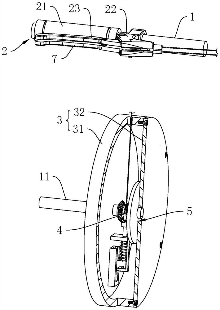
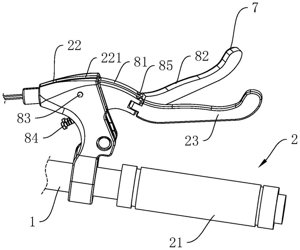
[0036] refer to figure 1 , including the main brake handle 2 installed on the frame 1 and the V-type brake assembly installed on the wheel frame, the main brake handle 2 is connected with the V-type brake assembly, and the main brake handle 2 is used to operate the V-type brake The brake assembly is used to decelerate the bicycle through the V-brake assembly.

[0037] refer to figure 1 , the brake feedback mechanism also includes a wheel shaft 11 rotatably installed on the wheel frame and an installation box 3 installed on the side of the wheel frame, and the installation box 3 includes a box body 31 fixed on the wheel frame by fasteners and fixed on the wheel frame by fasteners. The box cover 32 on the side of the box body 31, the installation box 3 is set as a hollow cylinder as a whole, one end of the wheel shaft 11 penetrates the center of the box body 31 and is rotatably connected w...

Embodiment 2

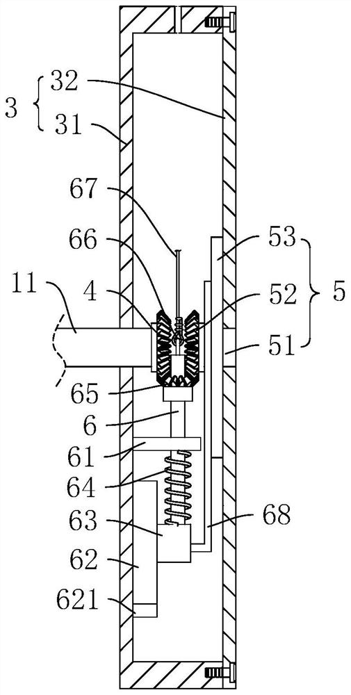
refer to Figure 4 , the difference between this embodiment and Embodiment 1 is that the utilization of braking energy is different. In this embodiment, a connecting rod 68 is fixed on the side of the reset block 63 away from the sliding seat 62 , one end of the connecting rod 68 is dislocated and extends above the flywheel shaft 51 , and the end of the connecting rod 68 is fixed with a deceleration plate 69 , and the deceleration plate 69 Arranged in an arc, the center of the deceleration plate 69 is disposed toward the axis of the flywheel shaft 51 .

[0049] The implementation principle of the second embodiment of the present application is as follows: when the auxiliary brake handle 7 is not firmly grasped, the reset block 63 is in the original position under the action of the reset spring 64, and the speed reduction plate 69 is in contact with the outer wall of the flywheel shaft 51 at this time. 69 Lock the flywheel shaft 51 to keep the flywheel 53 stationary during the ...


PUM


Abstract

The invention discloses a bicycle brake feedback mechanism, and belongs to the technical field of bicycle braking. The main brake handle is mounted on a frame, the V-shaped brake assembly is mounted on a wheel carrier, the wheel shaft and the mounting box are mounted on the wheel carrier, one end of the wheel shaft is rotatably connected with the mounting box, a driving gear is fixed to the end, located in the mounting box, of the wheel shaft, and a flywheel assembly is arranged on the inner wall of the mounting box. An auxiliary brake shaft is slidably connected to the inner wall of the mounting box in the vertical direction, a transmission gear is rotatably connected to the periphery of the auxiliary brake shaft, a reset assembly is arranged in the mounting box, one end of the auxiliary brake shaft is connected with a brake rope capable of driving the driving gear to be meshed with the transmission gear, and the end, away from the auxiliary brake shaft, of the brake rope is connected with an auxiliary brake handle. The flywheel assembly is used for decelerating the wheels, meanwhile, the energy of the flywheel assembly can be applied to bicycle starting, the starting difficulty of a rider is relieved, and the energy utilization rate is increased.

Description

technical field [0001] The present application relates to the technical field of bicycle braking, and in particular, to a bicycle brake feedback mechanism. Background technique [0002] Bicycles, also known as bicycles or bicycles, are usually small land vehicles with two wheels. After a person rides on a car, it is a green and environmentally friendly means of transportation that uses the pedals as power. Bicycles are generally composed of frames, tires, pedals, brakes, chains and other components. [0003] Bicycles in the related art usually use V-type brakes, and the main working principle is as follows: the brake wire is pulled through the handbrake to pull the brake frame inward, and then the brake pads on the brake frame will contact the sidewall of the wheel, and then The wheel is decelerated, and finally, when the brake is not needed, the wheel is braked by pushing out the spring to reset it. [0004] In view of the above-mentioned related art, the inventor believ...

Claims


Application Information

Patent Timeline
Patent Type & Authority Applications(China)
IPC IPC(8): B62L3/02B62M1/10
CPCB62L3/026B62M1/10
Inventor 林伟文郝勇李少斌凌峰史晓梅
Owner 深圳中华自行车(集团)股份有限公司
Why Eureka
Try Eureka