Water distribution ring pipe
A technology of water distribution ring and ring pipe, which is applied in the direction of hydroelectric power generation, impact engine, machine/engine, etc., can solve the problems of inconvenient model test, inability to quickly change the hydraulic flow channel, and inability to replace, so as to improve convenience and good performance Airtightness and the effect of preventing water leakage
- Summary
- Abstract
- Description
- Claims
- Application Information
AI Technical Summary
Problems solved by technology
Method used
Image

Examples
Embodiment 1
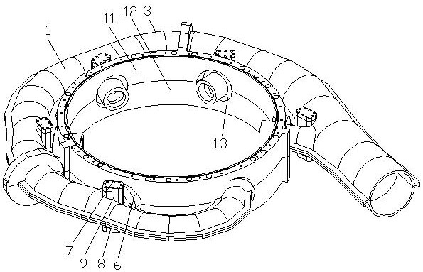
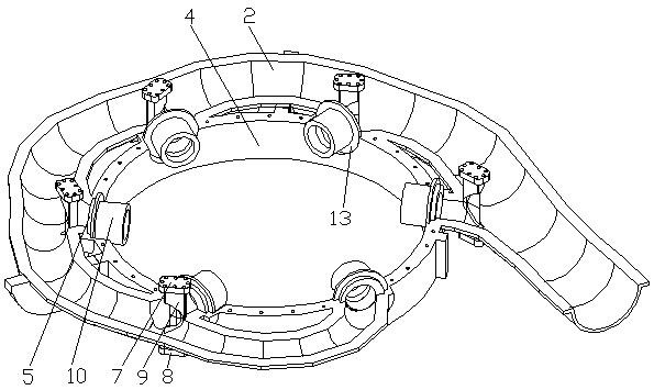
see figure 1 and figure 2 , a water distribution ring pipe, comprising the upper valve 1 of the water distribution ring pipe and the lower valve 2 of the water distribution ring pipe, the upper valve 1 of the water distribution ring pipe and the lower valve 2 of the water distribution ring pipe are connected to form the ring pipe body 3, and also include the runner chamber 4 and the angle Adjusting ring 5, a plurality of branch pipes 6 are connected to the ring pipe body 3, the branch pipes 6 are connected to the runner chamber 4 throughly, the top of the ring pipe body 3 is fixed with a first fixing seat 7, and the ring pipe body The bottom of the 3 is fixed with a second fixed seat 8, the first fixed seat 7 and the second fixed seat 8 are both located at the connection between the ring pipe body 3 and the fork pipe 6, and the first fixed seat 7 and the second fixed seat 8. A bifurcated pipe splitter plate 9 is embedded between them. The cross section of the bifurcated pipe ...
Embodiment 2
see figure 1 and figure 2 , a water distribution ring pipe, comprising the upper valve 1 of the water distribution ring pipe and the lower valve 2 of the water distribution ring pipe, the upper valve 1 of the water distribution ring pipe and the lower valve 2 of the water distribution ring pipe are connected to form the ring pipe body 3, and also include the runner chamber 4 and the angle Adjusting ring 5, a plurality of branch pipes 6 are connected to the ring pipe body 3, the branch pipes 6 are connected to the runner chamber 4 throughly, the top of the ring pipe body 3 is fixed with a first fixing seat 7, and the ring pipe body The bottom of the 3 is fixed with a second fixed seat 8, the first fixed seat 7 and the second fixed seat 8 are both located at the connection between the ring pipe body 3 and the fork pipe 6, and the first fixed seat 7 and the second fixed seat 8. A bifurcated pipe splitter plate 9 is embedded between them. The cross section of the bifurcated pipe ...
Embodiment 3
see figure 1 and figure 2 , a water distribution ring pipe, comprising the upper valve 1 of the water distribution ring pipe and the lower valve 2 of the water distribution ring pipe, the upper valve 1 of the water distribution ring pipe and the lower valve 2 of the water distribution ring pipe are connected to form the ring pipe body 3, and also include the runner chamber 4 and the angle Adjusting ring 5, a plurality of branch pipes 6 are connected to the ring pipe body 3, the branch pipes 6 are connected to the runner chamber 4 throughly, the top of the ring pipe body 3 is fixed with a first fixing seat 7, and the ring pipe body The bottom of the 3 is fixed with a second fixed seat 8, the first fixed seat 7 and the second fixed seat 8 are both located at the connection between the ring pipe body 3 and the fork pipe 6, and the first fixed seat 7 and the second fixed seat 8. A bifurcated pipe splitter plate 9 is embedded between them. The cross section of the bifurcated pipe ...
PUM
 Abstract
Description
Claims
Application Information