Piezoelectric transducer and medical equipment

A technology for piezoelectric transducers and medical equipment, applied in piezoelectric devices/electrostrictive devices, piezoelectric/electrostrictive/magnetostrictive devices, circuits, etc. The problem of limited insulation gap between the poles, affecting the energy conversion efficiency of the transducer, etc., can prolong the service life.

Pending Publication Date: 2022-06-03
ANYANG XIANGYU MEDICAL EQUIP
View PDF0 Cites 1 Cited by
  • Summary
  • Abstract
  • Description
  • Claims
  • Application Information

AI Technical Summary

Problems solved by technology

[0003] However, due to the thickness of the piezoelectric ceramic crystal, the positive and negative insulation gaps are limited, so the applied working voltage cannot be too large, otherwise it is easy to break down, resulting in the failure of the normal use of the transducer and affecting the life of the transducer. Large piezoelectric ceramic crystals will affect the energy conversion efficiency of the transducer
And during the working process, the electrical energy of the piezoelectric ceramic crystal is converted into mechanical energy of high-frequency vibration, which is easy to crack itself, resulting in a decrease in its own insulation performance and affecting the life of the transducer
[0004] In the prior art, the piezoelectric ceramic crystal of the transducer is generally potted with insulating glue to enhance insulation, but since the electrical energy of the piezoelectric ceramic crystal is converted into mechanical energy of high-frequency vibration, the insulating glue is easy to degrade with the piezoelectric ceramic crystal as time goes by. Detachment, limit the applied working voltage not to be too large, otherwise it is easy to break down, causing the transducer to not work normally, and then affecting the life of the transducer
And the piezoelectric ceramic crystal converts electrical energy into high-frequency vibration mechanical energy, and the metal coating on its surface falls in the form of powder around the crystal, destroying the insulation performance of the transducer and affecting the life of the transducer

Method used


Image

  • Piezoelectric transducer and medical equipment
  • Piezoelectric transducer and medical equipment
  • Piezoelectric transducer and medical equipment

Examples


Embodiment Construction

[0027] The following will clearly and completely describe the technical solutions in the embodiments of the application with reference to the drawings in the embodiments of the application. Apparently, the described embodiments are only some of the embodiments of the application, not all of them. Based on the embodiments in this application, all other embodiments obtained by persons of ordinary skill in the art without making creative efforts belong to the scope of protection of this application.

[0028] In order to enable those skilled in the art to better understand the solution of the present application, the present application will be further described in detail below in conjunction with the drawings and specific embodiments.

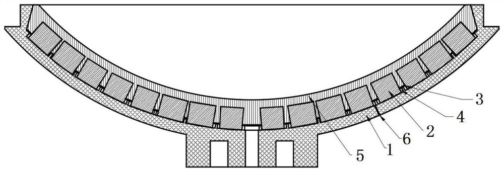
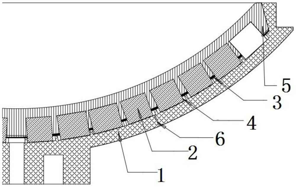
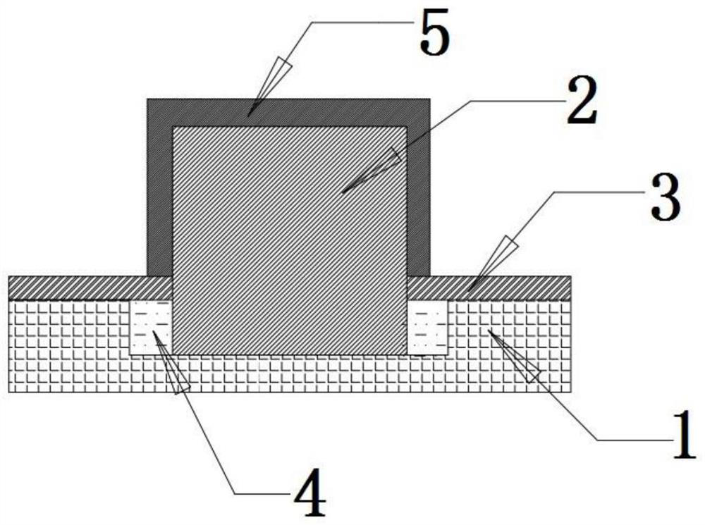
[0029] Reference manual attached Figure 1-5 , with figure 1 A schematic partial cross-sectional view of the piezoelectric transducer provided in the embodiment of the present application, figure 2 for figure 1 partial enlargement of the ima...


PUM


Abstract

The invention discloses a piezoelectric transducer and medical equipment, the piezoelectric transducer comprises a transducer shell, the inner surface of the transducer shell is provided with a plurality of mounting grooves used for mounting piezoelectric ceramic crystals, gaps exist between the mounting grooves and the piezoelectric ceramic crystals, and sealing insulation sheets are arranged in the gaps to seal the gaps. And filling a liquid insulating material between the sealing insulating sheet and the mounting groove, and pouring insulating glue into the inner wall of the transducer shell. The liquid insulator is filled between the positive electrode and the negative electrode of the piezoelectric ceramic crystal, so that the piezoelectric ceramic crystal can work under higher voltage, and higher energy is excited. And a self-repairing function is achieved through the liquid insulating substance, so that the service life of the piezoelectric transducer is greatly prolonged. Meanwhile, the sealing insulation sheet can be matched with a liquid insulator to reduce the risk of insulation failure caused by vibration of the piezoelectric ceramic crystal.

Description

technical field [0001] The present application relates to the field of piezoelectric medical equipment, in particular to a piezoelectric transducer and medical equipment. Background technique [0002] In the medical field, the principle of the commonly used piezoelectric extracorporeal shock wave therapy instrument is: the piezoelectric ceramic crystal is subjected to a high-voltage pulse volume change to generate a shock wave. When the high-voltage pulse passes through the piezoelectric ceramic crystal, its volume will change, and the movement of the ceramic crystal will form a pressure wave. When the ceramic crystal recovers, it will also form a tension wave. When hundreds of thousands of piezoelectric ceramic crystals move together When the shock wave is formed, the shock wave will be focused on one point under the action of the spherical device to form a high-energy shock wave. The shock wave passes through the focusing body to form a focused shock wave, which has a goo...

Claims


Application Information

Patent Timeline
Patent Type & Authority Applications(China)
IPC IPC(8): H01L41/053H01L41/09A61H23/02
CPCA61H23/008A61H23/02H10N30/883H10N30/88H10N30/20
Inventor 何永正魏吉忠徐昆仑康思远郭帅帅
Owner ANYANG XIANGYU MEDICAL EQUIP
Why Eureka
Try Eureka