
Anti-jitter robust beam forming optimization method for millimeter wave unmanned aerial vehicle communication system

A communication system and beamforming technology, applied in the field of anti-jitter robust beamforming optimization of millimeter wave unmanned aerial vehicle communication system, can solve the problems of low information transmission efficiency, instability, beam pointing deviation and the like of air-ground transmission link, Achieve the effect of guaranteeing service quality requirements and improving anti-jitter ability

Pending Publication Date: 2022-06-03
NANJING UNIV OF POSTS & TELECOMM
View PDF0 Cites 2 Cited by
  • Summary
  • Abstract
  • Description
  • Claims
  • Application Information

AI Technical Summary

Problems solved by technology

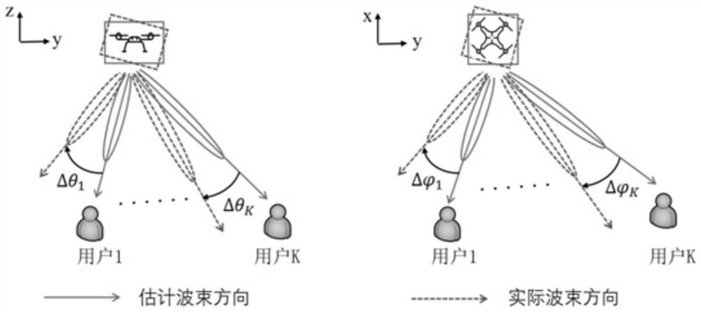
However, unlike terrestrial cellular networks with stable infrastructure, due to atmospheric turbulence and limitations in flight control capabilities, UAVs are susceptible to airflow and self-vibration, generating random jitter, such as yaw jitter in the horizontal direction or jitter in the vertical direction. Pitching jitter causes the angle deviation of the beam pointing, which in turn leads to inefficient and unstable air-to-ground transmission link information transmission

Method used


Image

  • Anti-jitter robust beam forming optimization method for millimeter wave unmanned aerial vehicle communication system
  • Anti-jitter robust beam forming optimization method for millimeter wave unmanned aerial vehicle communication system
  • Anti-jitter robust beam forming optimization method for millimeter wave unmanned aerial vehicle communication system

Examples


Embodiment Construction

[0058] In order to more fully understand the technical content of the present invention, the technical solutions of the present invention are further introduced and described below with reference to specific embodiments, but are not limited thereto.

[0059] In a first aspect, the present invention provides an anti-jitter robust beamforming optimization method for a millimeter-wave unmanned aerial vehicle communication system, including:

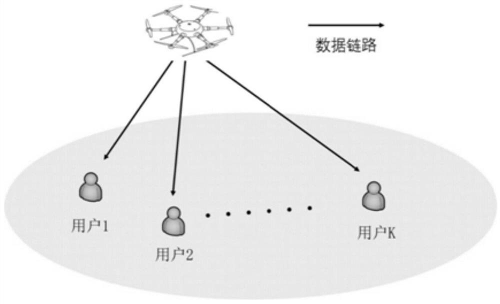
[0060] Receive GPS positioning and user backhaul channel feedback information in real time through the UAV millimeter-wave communication system, and analyze the millimeter-wave transmit beams transmitted by the multi-antenna UAV base station to multiple ground users in the feedback information. According to the millimeter-wave transmit beams, Obtain the UAV launch beamforming vector, and extract the position data of the UAV and ground users from the feedback information;

[0061] Calculate based on the location data of the UAV and the ground...


PUM


Abstract

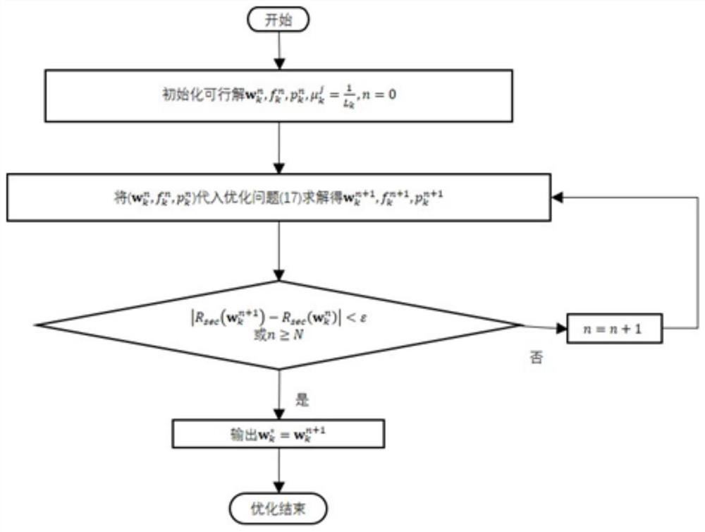
The invention discloses an anti-jitter robust beam forming optimization method for a millimeter wave unmanned aerial vehicle communication system, and the method comprises the steps: enabling the unmanned aerial vehicle millimeter wave communication system to receive the feedback information of GPS positioning and a user backhaul channel in real time, obtaining a beam forming vector transmitted by an unmanned aerial vehicle, obtaining the information of a pitch angle and an azimuth angle between the unmanned aerial vehicle and a ground user, and carrying out the anti-jitter robust beam forming optimization. The upper limit value of the unmanned aerial vehicle jitter error is obtained; importing a jitter error model, calculating the downlink transmission capacity sum of a plurality of ground users according to the unmanned aerial vehicle transmitted beam forming vector and the noise power, and determining a transmitted beam forming optimization problem; and carrying out deterministic transformation on an optimization problem of the jitter error model based on a convex hull theory, and solving by utilizing a continuous convex approximation method to obtain a beam forming vector parameter. According to the method, the unmanned aerial vehicle millimeter wave communication system with the optimal anti-jitter robust wave performance is determined based on the unmanned aerial vehicle millimeter wave transmitted beam forming optimization problem model with the known vector parameters, and the anti-jitter capability of the unmanned aerial vehicle millimeter wave communication system is improved.

Description

technical field [0001] The invention relates to the technical field of unmanned aerial vehicle millimeter wave communication, in particular to an anti-jitter robust beamforming optimization method of a millimeter wave unmanned aerial vehicle communication system. Background technique [0002] In recent years, the use of millimeter wave technology to implement UAV data communication has become a research hotspot in academia and industry. On the one hand, the short-wavelength and high-frequency characteristics of millimeter-wave signals provide a feasible solution for solving the problems of limited UAV loads and tight spectrum resources, which is conducive to improving the information transmission rate. On the other hand, UAVs can be flexibly arranged in the air, and the higher flight position makes the line-of-sight path often exist in the communication process, which can greatly expand the coverage of millimeter-wave communication and improve network connectivity, making it...

Claims


Application Information

Patent Timeline
Patent Type & Authority Applications(China)
IPC IPC(8): H04B7/06H04B7/185G06F17/17G06F17/11
CPCH04B7/0617H04B7/0621H04B7/18504G06F17/17G06F17/11Y02T10/40
Inventor 欧阳键倪单福潘阳阳衡晟玥王雪薇
Owner NANJING UNIV OF POSTS & TELECOMM
Learn More