Stacked lap joint process of sunlight room

A sun room, stacked technology, applied in the direction of general water supply saving, walls, buildings, etc., can solve the problems of low strength, difficult processing, dripping, etc., achieve high tensile and shear strength, and resist thermal deformation High capacity and long service life

Pending Publication Date: 2022-06-07
佛山市粤之枫建材有限公司
View PDF0 Cites 0 Cited by
  • Summary
  • Abstract
  • Description
  • Claims
  • Application Information

AI Technical Summary

Problems solved by technology

[0002] Most of the sunrooms on the market are made of frames that are directly overlapped, and dovetail grooves need to be cut for splicing. This is not only difficult to process, but when the span of the sunroom becomes larger, this kind of sunroom will not be able to be made; installation At the same time, the requirements for the installation workers are relatively high, which is time-consuming; only four screws can be screwed at most during installation. Over time, the sun room is prone to sinking; No drainage and seepage channels are added. When it rains or condensed water occurs, it cannot be discharged. It is easy to form large drops of water on the top surface and drop directly to the ground.
[0003] Moreover, the existing sun room still has the following disadvantages: 1. If the frame is directly overlapped, the indoor sealing effect is not ideal if it is fixed by the cone tail screw; 2. It is not possible to make a long-span sun room; 3. After a long period of wind blowing The sinking of the sun room is inevitable due to the rain, and it is easy to cause safety hazards. The strength is not high, the wind pressure resistance is weak, and the seismic effect is poor; 4. There is no drainage and seepage channel, and the rainwater is not easy to discharge; 5. On-site installation is complicated , very strict requirements for installers

Method used


Image

  • Stacked lap joint process of sunlight room
  • Stacked lap joint process of sunlight room
  • Stacked lap joint process of sunlight room

Examples


Embodiment Construction

[0026] The following in conjunction with the accompanying drawings in an embodiment of the present invention, the technical solution in the embodiment of the present invention is clearly and completely described, apparently, the embodiment described is only a part of the embodiment of the present invention, not all embodiments. Based on embodiments of the present invention, all other embodiments obtained by those of ordinary skill in the art without making creative labor, are within the scope of protection of the present invention.

[0027] The following embodiments of the present invention will be further described in detail in conjunction with the accompanying drawings, as detailed below:

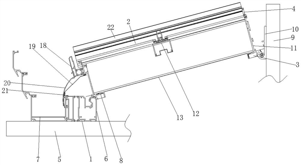
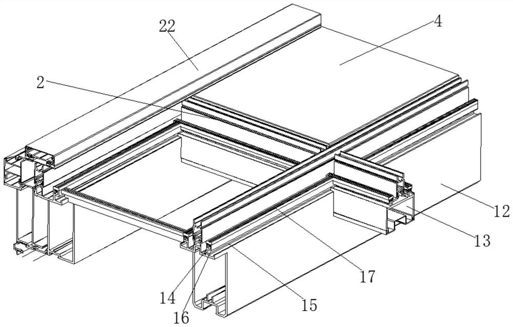
[0028] A kind of laminated lap process for sun room, which includes a front lap assembly 1, a skeleton assembly 2 and a rear lap assembly 3 set from bottom to top, between the skeleton assembly 2, between the front lap assembly 1 and the skeleton assembly 2 and between the rear lap assembly 3...


PUM


Abstract

According to the stacked type lap joint process for the sunlight room, a front beam is stacked on a window body, and a front transfer beam is stacked on the front beam; the main beam is stacked on the front transfer beam; the wall-leaning hook is connected with a wall body; the rear transfer beam is stacked on the wall-leaning hook; the main beams are stacked on the rear transfer beams, the stacking mode that the cross beams are in lap joint between the main beams and the hollow glass is in lap joint above the cross beams is different from the common sunlight room dovetail groove machining mode in the market at present, the stacking type lap joint technology is adopted, construction of workers can be more convenient and simpler, the overall sealing effect is guaranteed, and the construction efficiency is improved. The large-span sunlight room can be easily manufactured through stacked lap joint, it can be guaranteed that the overall performance of the large-span sunlight room is not changed, the overall load bearing performance of the sunlight room is improved, sinking of the sunlight room is avoided, and the large-span sunlight room has the advantages of being high in strength, free of deformation, low in cost and the like. The overall tensile strength, the shear strength and the thermal deformation resistance strength are high, and the service life can be effectively prolonged.

Description

Technical field [0001] The present invention relates to a sunlight room construction process, more particularly, to a laminated lap process for a sun room. Background [0002] Most of the sun rooms on the market are directly connected by frames, and the dovetail grooves need to be cut when lapping, which is not only difficult to process, but also when the span of the sun room becomes larger, such sun rooms will not be able to be made; Installation also has high requirements for installers and takes time; When installing, you can only hit four screws at most, and over time, the sun room is prone to sinking; At the same time, the effect of this type of sun room in sound insulation and heat insulation is not ideal, and there is no increase in drainage and seepage channels, which cannot be discharged when it rains and condenses, and it is easy to form large water droplets on the top surface and drip directly to the ground. [0003] And at present, the existing sun room still has the ...

Claims


Application Information

Patent Timeline
Patent Type & Authority Applications(China)
IPC IPC(8): E04B1/18E04B2/96E06B3/66E06B7/14
CPCE04B1/18E04B1/185E04B2/96E04B2/965E04B2/967E06B7/14E06B3/66Y02A20/108
Inventor 李昌安
Owner 佛山市粤之枫建材有限公司
Why Eureka
Try Eureka