Drain system for nuclear power plant

A nuclear power and discharge pump technology, which is applied in nuclear engineering, nuclear reactors, nuclear power generation, etc., can solve the problems of limiting the discharge speed of cooling medium and the cavitation phenomenon of discharge pumps, etc.

Inactive Publication Date: 2004-04-14
ABB COMBUSTION ENG NUCLEAR POWER
View PDF0 Cites 0 Cited by
  • Summary
  • Abstract
  • Description
  • Claims
  • Application Information

AI Technical Summary

Problems solved by technology

Such a vortex is undesirable as it limits the rate at which the cooling medium can be drained from the drain system and may eventually cause cavitation in the drain pump

Method used


Image

  • Drain system for nuclear power plant
  • Drain system for nuclear power plant
  • Drain system for nuclear power plant

Examples


Embodiment Construction

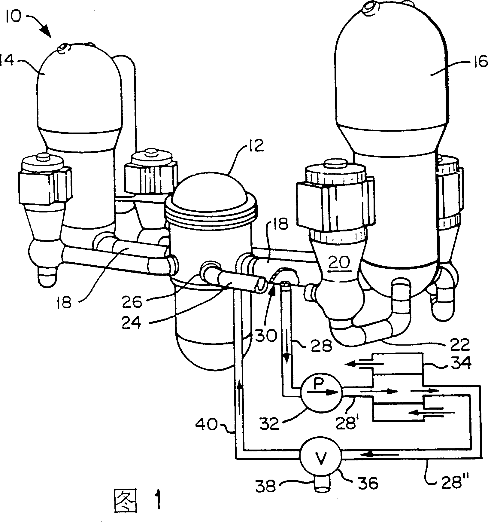
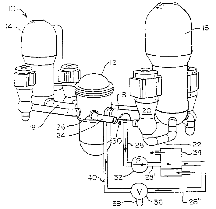
[0019] Figure 1 shows a nuclear power plant incorporating the present invention. Numeral 10 generally denotes a pressurized water reactor type nuclear power plant. Here, water is continuously conveyed through a closed loop between the reactor 12 and each of the two evaporative generators 14 and 16 .

[0020] The water cooling medium flows from the reactor 12 through the main pipe or heat pipe 18 to the steam generators 14 and 16 respectively. Each evaporative generator has similar piping.

[0021] Now take the steam generator 16 as an example to illustrate, the cooling medium system circulation pump 20 circulates the water cooled in the steam generator to flow through an absorption pipe 22, and returns to the reactor 12 through the cold pipe 24 and the inlet 26 .

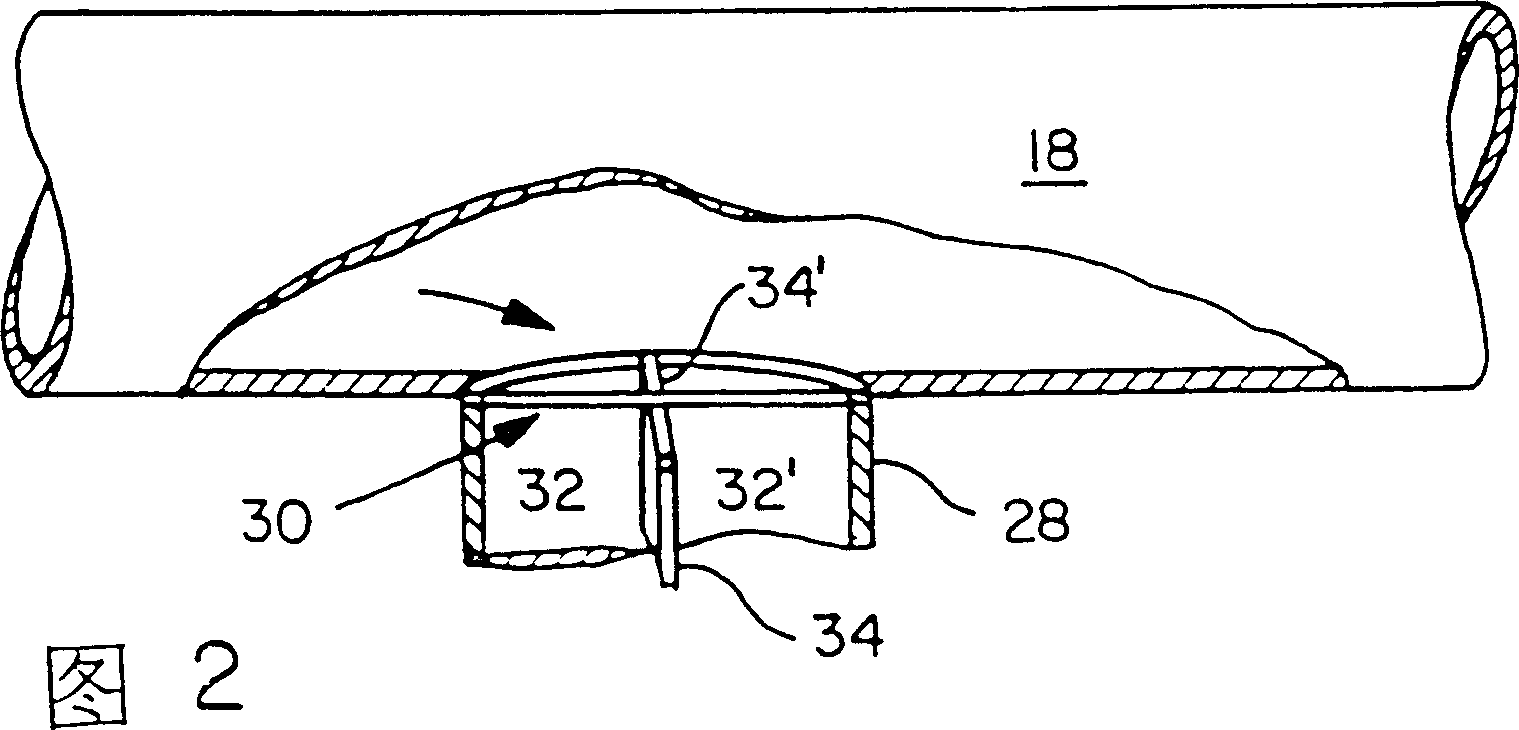
[0022] The shutdown cooling system drain pipe 28 intersects the lower section of the substantially horizontal main or thermal pass pipe 18 . Immediately adjacent to but not within the lower section of main condu...


PUM


Abstract

A drain system for a shutdown cooling system of a pressurized water reactor type of a nuclear power plant (10) has an increased flow rate in the drain pipe (28) and drain pump (33). The hot leg (18) connected drain pipe has a vaned vortex breaker (30) mounted therein between its connection with the hot leg (18) lower region and the drain pump (32). This minimizes vortex-created cavitation in the drain pump thereby permitting the increased flow rate.

Description

technical field [0001] The invention relates to a high-efficiency drainage system suitable for the pressurized water shutdown cooling system of a nuclear power station. Specifically, the present invention can minimize the cavitation phenomenon caused by the coriolis effect (coriolis effect) vortex in the discharge pump of the shutdown cooling system, thereby increasing the flow rate of the cooling medium in the discharge system. Background technique [0002] In a pressurized water reactor (PWR) type nuclear power plant, the cooling medium fluid is essentially boron plus water, which is continuously transported through a closed loop between a nuclear reactor and one or more steam generators. [0003] During nuclear power production, the pressurized cooling medium absorbs the heat released by the thermonuclear reactions taking place in the reactor. The heated cooling medium then flows through a main pipe, aptly called the "heat leg" of the circulation loop. The heat pipe sup...

Claims


Application Information

Patent Timeline
Patent Type & Authority Patents(China)
IPC IPC(8): G21C19/28
CPCG21Y2004/302G21Y2002/207G21Y2002/50G21Y2002/40G21C19/28Y02E30/30G21C1/03
Inventor D·A·帕克
Owner ABB COMBUSTION ENG NUCLEAR POWER
Why Eureka
Try Eureka