Direct insertion type sealed circular electric connector

An electrical connector and in-line technology, applied in the direction of connection, two-part connection device, parts of the connection device, etc., can solve the production work that cannot be realized quickly, the production work of stamping processing is inconvenient, and the work of mechanical processing is unfavorable and other problems, to achieve the effect of separating transmission work, efficient production work, and realizing split production

Inactive Publication Date: 2022-06-07
PEACEFUL VISION ELECTRONICS LIANYUNGANG
View PDF3 Cites 0 Cited by
  • Summary
  • Abstract
  • Description
  • Claims
  • Application Information

AI Technical Summary

Problems solved by technology

[0007] It is inconvenient to carry out continuous production work, it is not conducive to machining work, it is impossible to realize rapid production work, and it is inconvenient to cooperate with stamping processing production work, so an in-line, sealed circular electrical connector is needed to solve questions raised in the above

Method used


Image

  • Direct insertion type sealed circular electric connector
  • Direct insertion type sealed circular electric connector
  • Direct insertion type sealed circular electric connector

Examples


Embodiment 1

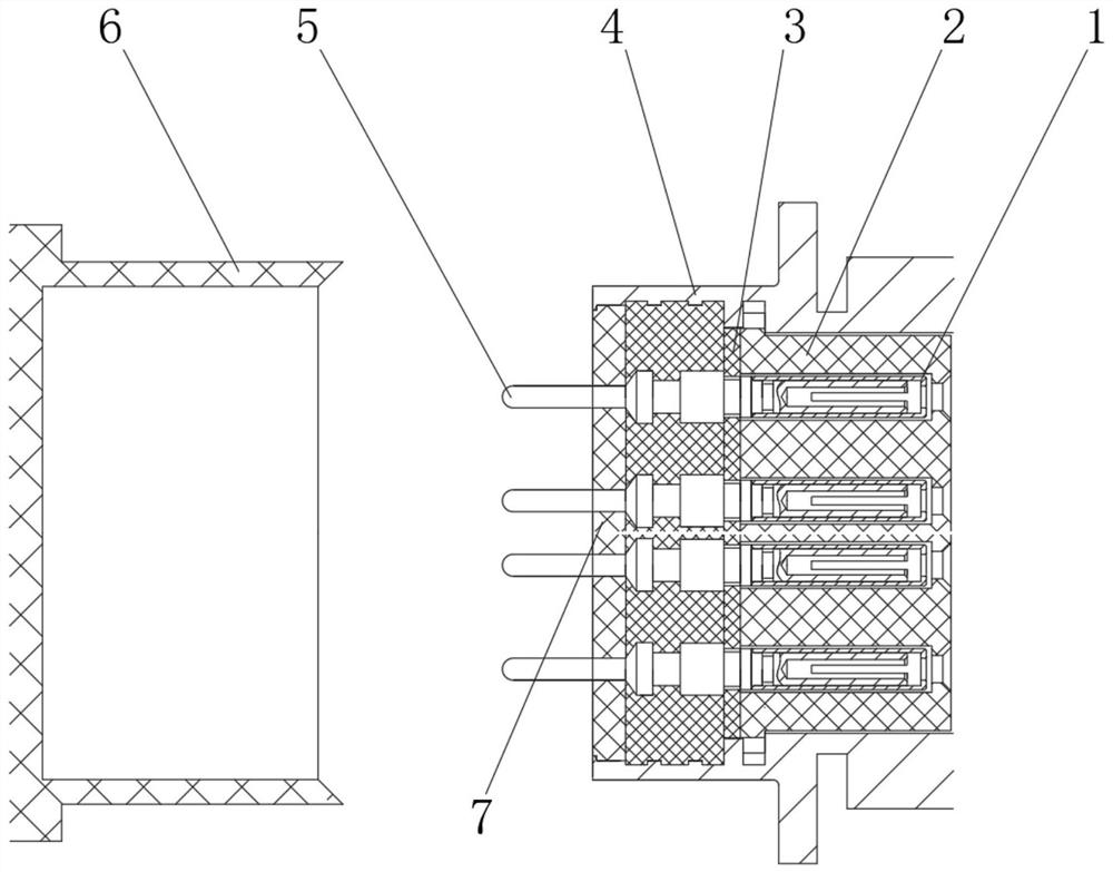
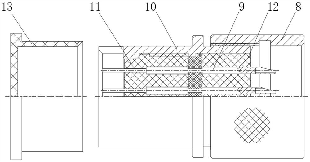
[0052] See Figure 1 、 Figure 2 , an embodiment of the present invention provided: an in-line, sealed circular electrical connector, including plugs and sockets, by connection combination, to facilitate the overall installation combination;

[0053] The socket comprises a sheath 1, an insulator under the socket 2, a rubber pad 3, a seat housing 4, a jack 5, a first protective cap 6 and an insulator on the socket 7;

[0054] The side end position of the sheath 1 is fixedly connected to the insulator under the socket 2, the bottom end of the sheath 1 is fixed to the jack 5, the side end of the insulator 2 under the socket is fixed with the rubber pad 3, the side end of the rubber pad 3 is fixed to the insulator 7 on the socket, the rubber pad 3, the outer end of the insulator 7 on the socket is set with the seat shell 4, and the side end position of the jack 5 is provided with the first protective cap 6, which is convenient for forming and connecting work through the setting of the s...

Embodiment 2

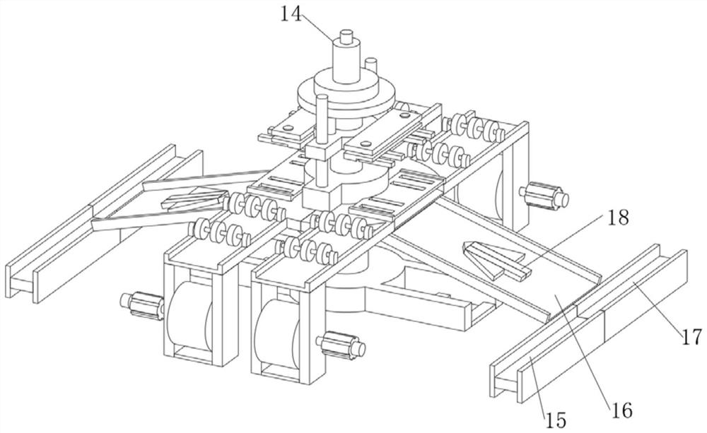
[0070] On the basis of Example 1, e.g., Figure 10 As shown, the side end position of the pressing production member 14 is fixedly connected to the supporting top plate frame 40, and the lower end of the supporting top plate frame 40 is fixedly connected to the protective incline frame 39.

[0071]In the present embodiment, by installing the protective bevel frame 39 and the support top plate frame 40, the protective bevel frame 39 is fixedly connected to the pressing production component 14 by supporting the top plate frame 40, to achieve the support installation work at the side end, and the setting of the protective slash 39 can realize the capping treatment of the upper part of the tilt frame 16, which is conducive to reducing the dust of the upper part, facilitating the dust-free production work, and at the same time facilitating the protection work to prevent the edge of the production material from falling.

[0072] Working principle: the user will press the production parts...


PUM


Abstract

The invention relates to the technical field of connector equipment, and discloses a direct insertion type sealed circular electric connector, which comprises a plug and a socket, and is characterized in that the socket comprises a sheath, a socket lower insulator, a rubber pad, a seat shell, a jack, a first protective cap and a socket upper insulator, and the side end position of the sheath is fixedly connected with the socket lower insulator; the bottom end of the sheath is fixedly connected with the jack, the side end of the socket lower insulator is fixedly connected with the rubber pad, the side end of the rubber pad is fixedly connected with the socket upper insulator, the outer ends of the rubber pad and the socket upper insulator are wrapped with the socket shell, and the side end of the jack is provided with a first protective cap. The plug comprises a locking sleeve, a pin, a head shell, a plug lower insulator, a plug upper insulator and a second protective cap, the plug lower insulator is arranged at the side end of the second protective cap, and the top end of the plug lower insulator is fixedly connected with the head shell. Through the arrangement of the structure, connection production operation is achieved.

Description

Technical field [0001] The present invention relates to the technical field of connector equipment, specifically a in-line, sealed circular electrical connector. Background [0002] The electrical connector structure is a straight push-in and pull-out structure, and there is a self-locking function after insertion. It has the characteristics of fast insertion, high density, small volume and blind insertion, which is especially suitable for high-density installation, small space installation and the use of rotary mode to insert and separate the occasion. Suitable for radio equipment, medical equipment, testing equipment, audio and video equipment, data acquisition, industrial control and other occasions of DC or AC circuit electrical connection, the original product lack of insulators, only the use of epoxy resin glue potting process, due to the assembly of the operator filling techniques of different processes, glue batches are different and other reasons, different batches of as...

Claims


Application Information

Patent Timeline
Patent Type & Authority Applications(China)
IPC IPC(8): H01R43/20H01R13/03H01R13/629H01R24/00H01R43/00
CPCH01R43/20H01R13/03H01R13/629H01R24/00H01R43/00Y02T90/14
Inventor 陈祥常鑫张瑞
Owner PEACEFUL VISION ELECTRONICS LIANYUNGANG
Why Eureka
Try Eureka