Trimming device and wafer polishing system

A technology for dressing devices and wafers, applied in grinding devices, grinding drive devices, grinding/polishing equipment, etc., can solve the problems of poor wafer polishing effect and inability to judge the degree of wear of polishing pads, etc.

Pending Publication Date: 2022-06-17
BEIJING SEMICORE PRECISION MICROELECTRONICS EQUIP CO LTD
View PDF7 Cites 0 Cited by
  • Summary
  • Abstract
  • Description
  • Claims
  • Application Information

AI Technical Summary

Problems solved by technology

[0005] Therefore, the technical problem to be solved by the present invention lies in the defect in the prior art that the polishing pad with excessive wear cannot be used to polish the wafer due to the inability to judge the degree of wear of the polishing pad, thereby making the wafer polishing effect poor

Method used


Image

  • Trimming device and wafer polishing system
  • Trimming device and wafer polishing system

Examples


Embodiment 1

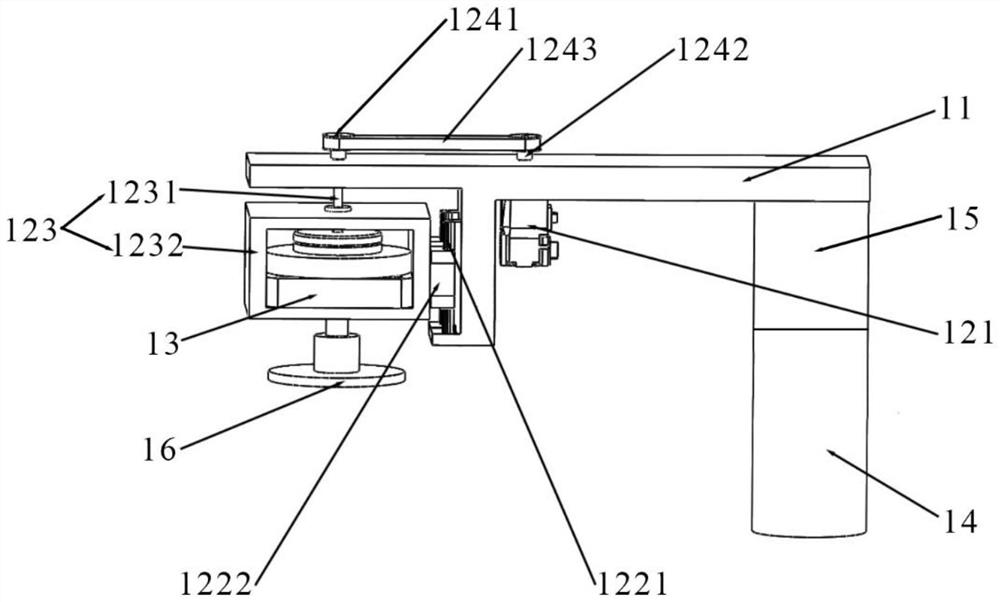
[0038] This embodiment provides a trimming device, such as figure 2 As shown, it includes a mounting frame 11, a lifting mechanism and a detection member. The cross section of the mounting frame 11 is T-shaped. The lifting driving mechanism has a lifting driving member 121. The lifting driving member 121 is a servo motor. On the right side of the mounting frame 11 , the lift driving member 121 drives the grinding head 16 to approach the polishing pad 4 .

[0039] like figure 2 As shown, in the trimming device provided in this embodiment, the lifting mechanism further includes a sliding component, a lead screw structure 123, and an overload prevention component. The overload prevention component is arranged on the top surface of the mounting frame 11. The overload prevention component includes a belt 1243, a first The pulley 1241 and the second pulley 1242, the drive shaft of the lift driving member 121 is fixedly connected to the first pulley 1241 through the mounting frame...

Embodiment 2

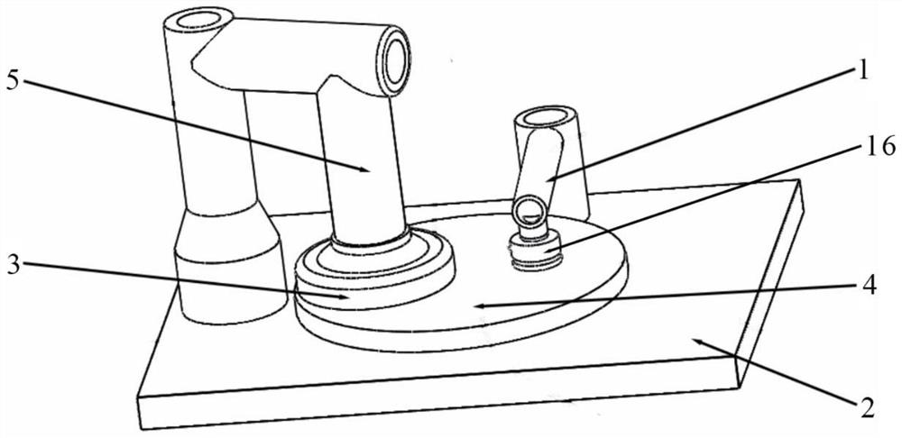
[0047] This embodiment provides a wafer 3 polishing system such as figure 1 As shown, the trimming device 1 of Example 1 is included.

[0048] like figure 1 As shown, the wafer 3 polishing system provided in this embodiment further includes a base 2, a wafer 3 and a polishing device 5. The trimming device 1 is arranged at one end of the base 2, and the polishing pad 4 is arranged in the middle of the base 2. The polishing device 5 is disposed on the other end of the base 2 , and the polishing end of the polishing device 5 is pressed against the wafer 3 , and the wafer 3 is placed on the polishing pad 4 .

[0049] In the wafer 3 polishing system provided in this embodiment, since the dressing device 1 can provide accurate data for replacing the polishing pad 4 , it is avoided to use the excessively worn polishing pad 4 to polish the wafer 3 , thereby improving the polishing effect of the wafer 3 , further improving the yield of wafer 3 .


PUM


Abstract

The invention discloses a trimming device and a wafer polishing system.The trimming device comprises a mounting frame, a lifting mechanism and a detection piece, the lifting mechanism is provided with a lifting driving piece, the mounting end of the lifting driving piece is connected with the mounting frame, and the driving end of the lifting driving piece is suitable for being connected with a grinding head; the lifting driving piece has a grinding state for driving the grinding head to be close to or away from the polishing pad; the detection piece is suitable for forming position information according to the detected displacement distance of the grinding head, the lifting driving piece drives the grinding head to move towards the polishing pad until the polishing pad abuts against the grinding head, the abrasion degree of the polishing pad is increased along with grinding and polishing work, and the lifting driving piece drives the grinding head to abut against the polishing pad all the time. A worker can accurately judge the abrasion degree of the polishing pad according to the displacement distance change detected by the detection piece, so that the polishing pad is replaced in time, and the situation that the polishing pad which is excessively abraded is used for polishing a wafer is avoided.

Description

technical field [0001] The invention relates to the technical field of semiconductor processing, in particular to a trimming device and a wafer polishing system. Background technique [0002] In the process of manufacturing semiconductor devices, the wafer needs to be polished and ground. Chemical mechanical polishing is a process of contacting the wafer with the surface of the polishing pad, and then flattening the surface of the wafer through the relative motion between the surface of the wafer and the surface of the polishing pad. At present, the industry usually uses the polishing pad adjustment device of the chemical mechanical polishing equipment to adjust the flatness of the polishing surface of the polishing pad. [0003] The prior art polishing pad adjustment device includes a connecting beam, a lifting cylinder, a motor mounting frame, a servo motor and a grinding head, one end of the connecting beam is fixed with a lifting cylinder, a driving end of the lifting cy...

Claims


Application Information

Patent Timeline
Patent Type & Authority Applications(China)
IPC IPC(8): B24B37/10B24B53/017B24B47/12B24B49/12B24B47/22B24B7/22
CPCB24B37/10B24B53/017B24B47/12B24B49/12B24B47/22B24B7/228
Inventor 于静王文举李婷廉金武赵磊樊八涛
Owner BEIJING SEMICORE PRECISION MICROELECTRONICS EQUIP CO LTD
Why Eureka
Try Eureka