Portable cooling unit

A cooling unit, portable technology, applied in the direction of coolers, refrigerators, refrigeration components, etc., can solve the problems of fixed systems that do not allow operation, damage, lack of transportable cooling units, etc.

Pending Publication Date: 2022-06-21
SECOP GMBH
0 Cites 0 Cited by

AI-Extracted Technical Summary

Problems solved by technology

[0006] Also, stationary systems do not allow operation in a tilted orientation, i.e., they are not portable
Conversely, this inclination leads to failure or damage to stationary systems
[0007] Therefore, there is a lac...

Abstract

A portable cooling unit for transporting temperature-sensitive goods while maintaining a desired cooling temperature, comprising a multi-stage cascade refrigeration system adapted to operate during transportation of the portable cooling unit and adapted to be cooled to and maintained at a temperature more than 70 K lower than ambient temperature, a suspension system adapted and arranged to act as an elastic support of the multi-stage cascade refrigeration system and/or a component of the multi-stage cascade refrigeration system, a motion defining system adapted and arranged to limit motion of the multi-stage cascade refrigeration system and/or components of the multi-stage cascade refrigeration system, an impact protection system adapted and arranged to buffer collisions between the multi-stage cascade refrigeration system and other components of the portable cooling unit and/or between components of the multi-stage cascade refrigeration system, a lubrication system that facilitates lubrication of components of the multi-stage cascade refrigeration system for an inclination that deviates from a horizontal orientation of the portable cooling unit by at least 10 DEG, and a monitoring system adapted to generate an alert signal in the event of a failure of the portable cooling unit.

Application Domain

CompressorDomestic refrigerators

Technology Topic

Cooling temperatureLubrication +5

Image

  • Portable cooling unit
  • Portable cooling unit
  • Portable cooling unit

Examples

  • Experimental program(1)

Example Embodiment

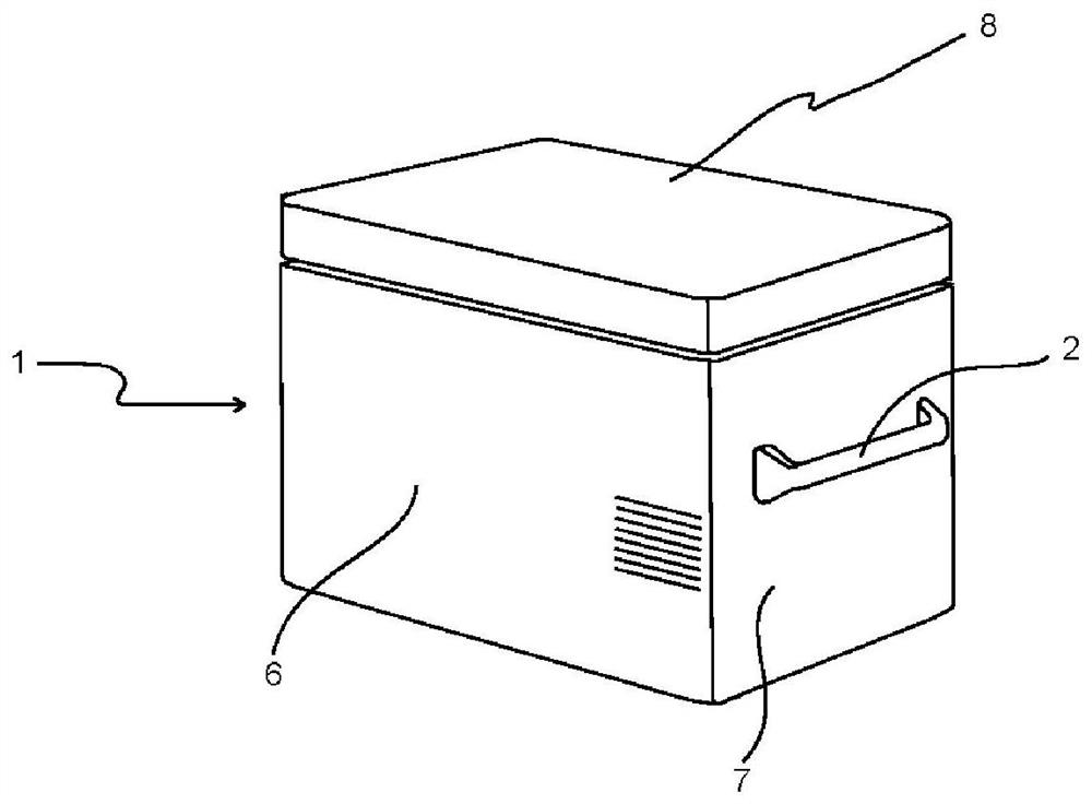
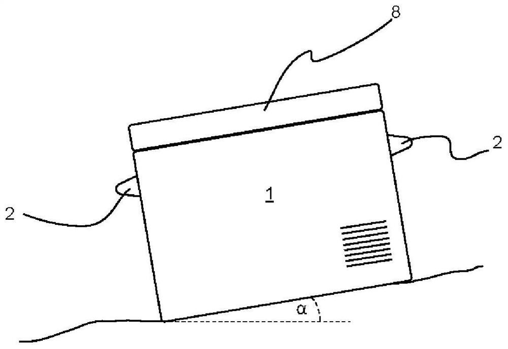
[0044] figure 1 A portable cooling unit 1 according to the invention is shown, characterized by having two handles 2 ( figure 1 Only one of them is visible, see figure 2 ). The cooling unit 1 is divided into an insulated cooling chamber 6, in which highly temperature-sensitive goods are stored during transport, and a separate machinery chamber 7, which accommodates a multi-stage cascade refrigeration system. The cooling chamber 6 is closed off from the ambient air by a door 8 .
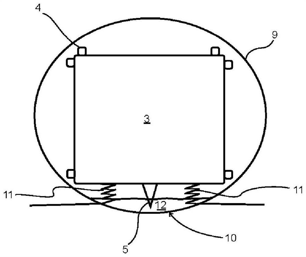
[0045] The multi-stage refrigeration system may be implemented as a two-stage cascade refrigeration system including two vapor compression refrigeration systems respectively forming a high temperature refrigeration cycle and a low temperature refrigeration cycle. Each of these refrigeration cycles includes such as figure 2 Compressor of the design shown.
[0046] exist figure 2 , the compressor is shown comprising a compressor housing 9 and a motor compression unit 3 elastically suspended on a base 10 of the compressor housing 9 by means of a plurality of springs 11 forming a suspension system. The motor compression unit 3 is characterized by a plurality of spacer elements 4 made of elastic material which are arranged on the outer surface of the motor compression unit 3 and protrude from said outer surface towards the compressor housing 9 . These spacer elements 4 serve as an impact protection system, since their elastic design buffers any impact between the elastically suspended motor compression unit 3 and the compressor housing 9 . At the same time, the spacer element 4 can be used as a motion-defining system by selecting the dimensions of the spacer element 4 such that only a predetermined displacement from the rest position of the motor compression unit 3 is allowed ( Figure 4 ).
[0047] also, figure 2 and 4 A lubricant container 5 is schematically shown attached to the crankshaft (not shown) of the motor compression unit 3 such that the lubricant container 5 protrudes into the lubricant groove 12 of said compressor. This lubricant container 5 - possibly together with other means for lubricant delivery, such as grooves in the crankshaft surface, eccentric holes and/or outlet openings in the crankshaft - forms a lubrication system. Said lubrication system ensures stable lubrication of the motor compression unit 3 (or its components), even in the case where the portable cooling unit 1 is tilted by an angle α from a horizontal orientation (eg image 3 and 4 shown). Although compressors used in stationary (fixed-position) refrigeration systems may risk serious damage due to lack of lubrication at certain inclinations, at least part of the bottom area of ​​the compression unit 3 will no longer be submerged due to the motor the lubricant groove 12, so the lubricant container 5 still protrudes into the lubricant groove 12 even at this inclination ( Figure 4 ).
[0048] Since it is necessary to immediately detect and eliminate the failure of the portable cooling unit 1 in order to prevent highly temperature-sensitive goods (eg vaccines) from being damaged or become unavailable, the portable cooling unit 1 also includes an Surveillance system for alarm signals. The warning signal can be generated, for example, when a certain increase in temperature in the cooling chamber is detected, and/or a certain inclination angle α is exceeded, and/or a certain ambient temperature is exceeded.

PUM

no PUM

Description & Claims & Application Information

We can also present the details of the Description, Claims and Application information to help users get a comprehensive understanding of the technical details of the patent, such as background art, summary of invention, brief description of drawings, description of embodiments, and other original content. On the other hand, users can also determine the specific scope of protection of the technology through the list of claims; as well as understand the changes in the life cycle of the technology with the presentation of the patent timeline. Login to view more.
Why Eureka
Try Eureka