Supercharge Your Innovation With Domain-Expert AI Agents!

High-reliability microwave signal detection circuit

A technology of microwave signal and detection circuit, which is applied in the field of signal processing, can solve problems such as the inability to effectively prevent radio frequency signal coupling and crosstalk, and achieve the effects of improving dynamic detection range and reliability, improving sensitivity, and reducing void rate

Pending Publication Date: 2022-06-21
SHENZHEN ZHENHUA MICROELECTRONICS
View PDF0 Cites 0 Cited by
  • Summary
  • Abstract
  • Description
  • Claims
  • Application Information

AI Technical Summary

Problems solved by technology

Due to the small size of the substrate of RF products, RF signals are prone to coupling or crosstalk, which interferes with the comparison point voltage at the negative input terminal of the comparator in the microwave signal detection circuit and affects the detection results. According to the existing microwave detection circuit topology, when the input power When it is small, the radio frequency signal will be coupled to the negative input terminal of the voltage comparator. When the input power is large, the detection voltage may affect the voltage of the comparison point. It is difficult to detect the fluctuation of the input terminal of the voltage comparator with the existing structure due to the interference of the radio frequency signal. At the same time, it is impossible to effectively prevent the coupling and crosstalk of RF signals, which will affect the reliability of the detection circuit

Method used


Image

  • High-reliability microwave signal detection circuit
  • High-reliability microwave signal detection circuit

Examples


Embodiment Construction

[0025] In order to describe the technical solutions of the present invention more clearly and completely, the present invention is further described below with reference to the accompanying drawings.

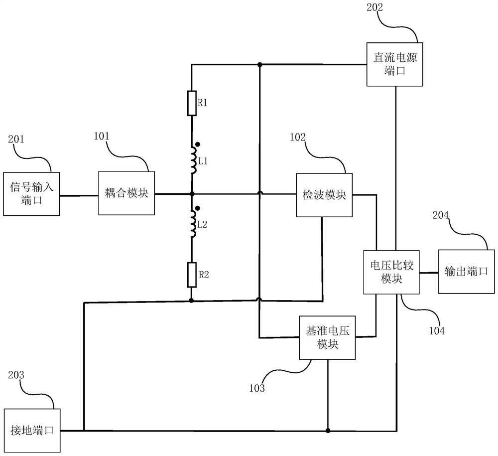
[0026] See figure 1 The present invention proposes a highly reliable microwave signal detection circuit embodiment, including: a signal input port 201, a DC power port 202, a ground port 203, an output port 204, a coupling module 101, a detection module 102, a reference voltage module 103, a voltage The comparison module 104, the first resistor R1, the second resistor R2, the first inductor L1 and the second inductor L2. The signal input port 201 is used for accessing radio frequency signals, the DC power port 202 is used for accessing an external DC power supply, and the ground port 203 is used for power supply and signal grounding. The first end of the coupling module 101 is connected to a signal input port for coupling and inputting a radio frequency signal. The first end o...


PUM


Abstract

The invention provides a high-reliability microwave signal detection circuit which comprises a signal input port, a direct-current power supply port, a grounding port, an output port, a coupling module, a detection module, a reference voltage module, a voltage comparison module, a first resistor, a second resistor, a first inductor and a second inductor. The two choke inductors are additionally arranged at the input voltage dividing end, eutectic welding is adopted in the component structure welding process, the precision of comparison point voltage and the sensitivity of the detector diode are improved, and the dynamic detection range and reliability of a product are improved.

Description

technical field [0001] The invention relates to the field of signal processing, in particular to a highly reliable microwave signal detection circuit. Background technique [0002] The RF signal is a high-frequency signal, and the microwave signal detection circuit can be used to detect the amplitude of the RF signal. When the input level is within the specified range, the output level is TTL low level. When the input level exceeds the specified range, the output level The TTL level is flipped, thereby making a detection indication. Due to the small size of the substrate of the RF product, the RF signal is prone to coupling or crosstalk, which interferes with the comparison point voltage at the negative input end of the comparator in the microwave signal detection circuit and affects the detection result. According to the existing microwave detection circuit topology, when the input power When it is small, the radio frequency signal will be coupled to the negative input ter...

Claims


Application Information

Patent Timeline
Patent Type & Authority Applications(China)
IPC IPC(8): G01R19/165G01R1/30
CPCG01R19/16576G01R1/30
Inventor 任纪元涂小军郭振
Owner SHENZHEN ZHENHUA MICROELECTRONICS
Features
  • R&D
  • Intellectual Property
  • Life Sciences
  • Materials
  • Tech Scout
  • Unparalleled Data Quality
  • Higher Quality Content
  • 60% Fewer Hallucinations
Learn More